Exhaust gas treatment for an internal combustion engine

a technology for exhaust gas treatment and internal combustion engines, which is applied in the direction of exhaust treatment electric control, electrical control, machines/engines, etc., can solve the problems of significantly incorrect particle load determination, actual conditions can deviate from the determined conditions,

Active Publication Date: 2020-10-20
VITESCO TECH GERMANY GMBH
View PDF18 Cites 1 Cited by
  • Summary
  • Abstract
  • Description
  • Claims
  • Application Information

AI Technical Summary

Benefits of technology

[0010]In one embodiment, the oxygen storage capacity of the catalytic converter comprises steps of operating, in a first phase, the internal combustion engine with excess fuel in order to reduce, if appropriate, oxygen stored in the catalytic converter, and of operating, in a second phase, the internal combustion engine with excess oxygen in order to permit the storage of oxygen in the catalytic converter, and of determining the storage capacity on the basis of the oxygen contents of the exhaust gas upstream and downstream of the catalytic converter during the second phase. In order to implement these method steps, a first lambda probe upstream of the catalytic converter and a second downstream are essentially sufficient. The determination of the oxygen storage capacity can be carried out easily and quickly.
[0013]The processing device can comprise, in particular, a programmable microcomputer which is preferably configured to carry out, for example by means of the computer program product described above, the method which is described further above. The regeneration of the particle filter can be brought about by making available a corresponding message to a control device for the internal combustion engine. In a further embodiment, the control devices for the particle filter and for the internal combustion engine are integrated with one another, with the result that the regeneration of the particle filter can be brought about or actuated directly.

Problems solved by technology

However, since the particle load of the particle filter is not measured in this way but instead only tracked, the actual conditions can deviate from the determined conditions.
The actual particle emissions of the internal combustion engine can change over its service life or owing to a fault, with the result that a significantly incorrect particle load can be determined.

Method used


Image

  • Exhaust gas treatment for an internal combustion engine
  • Exhaust gas treatment for an internal combustion engine

Examples


Embodiment Construction

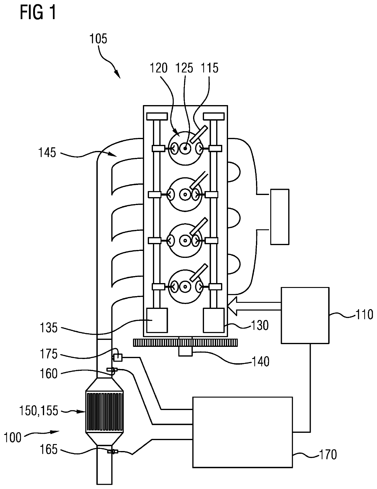
[0020]FIG. 1 shows a system 100 for controlling an internal combustion engine 105. The internal combustion engine 105 is preferably configured to drive a motor vehicle and is more preferably embodied as a spark ignition engine. A first control device 110 is configured to control the internal combustion engine 105, in particular an operating point of the internal combustion engine 105. For this purpose, it is possible to influence different components of the internal combustion engine 105, for example an injector 115 for injecting a predetermined quantity of fuel into a combustion chamber 120, an ignition device 125 for igniting a mixture of fuel and oxygen in the combustion chamber 120 at a predetermined time, an inlet adjustment means 130 for influencing an inlet time of air into the combustion chamber 120, an out adjustment means 135 for influencing an outlet time of exhaust gas from the combustion chamber 120 and, if appropriate, other components also. The control can be carried ...


PUM


Abstract

An internal combustion engine makes available exhaust gas which can be treated by means of a catalytic converter and a particle filter. A method for determining the particle load of the particle filter comprises steps of determining the storage capacity of the catalytic converter for oxygen and determining the particle load of the particle filter on the basis of the determined storage capacity in the controller.

Description

CROSS-REFERENCE TO RELATED APPLICATIONS[0001]This application claims the benefit of PCT Application PCT / EP2016 / 074180, filed Oct. 10, 2016, which claims priority to German Patent Application 10 2015 219 777.8, filed Oct. 13, 2015.FIELD OF THE INVENTION[0002]The invention relates to the exhaust gas treatment of an internal combustion engine. In particular, the invention relates to a particle filter in the exhaust gas stream of the internal combustion engine.BACKGROUND OF THE INVENTION[0003]An internal combustion engine, in particular a reciprocating piston engine, which is configured, for example, to drive a motor vehicle, burns a mixture of fuel and oxygen. In this context, an exhaust gas is produced which is treated in a catalytic converter in order to reduce emitted pollutants. In order to be able to operate the catalytic converter efficiently, the oxygen content of the exhaust gas is determined and the internal combustion engine is controlled in such way that a predetermined comb...

Claims


Application Information

Patent Timeline
Patent Type & Authority Patents(United States)
IPC IPC(8): F01N9/00F01N13/00F01N3/035F02D41/02F02D41/14F01N3/10
CPCF02D41/1446F01N3/035F02D41/1454F02D41/1441F02D41/1445F01N3/101F02D41/0235F01N9/002F02D41/029F01N2900/1411Y02T10/40F01N2560/025F01N2900/1606F01N2900/1624F01N13/009F01N2900/1404F02D2200/0812F02D2200/0816F01N2560/14Y02T10/12F01N2560/06
Inventor NIENHOFF, MICHAELRODATZ, PAULZHANG, HONGCHEN, HAO
Owner VITESCO TECH GERMANY GMBH
Why Eureka
Try Eureka