Reciprocating electric razor head

a razor head and electric technology, applied in the direction of metal working devices, etc., can solve the problems of inability to implement other process structures, ultra-thin thickness of fixed blades, etc., and achieve the effects of simple processes for making and processing fixed blades, low rigidity requirements, and clean removal

Active Publication Date: 2020-12-08
LITTLE STONE CERAMIC BLADE ZHONGSHAN CO LTD
View PDF21 Cites 10 Cited by
  • Summary
  • Abstract
  • Description
  • Claims
  • Application Information

AI Technical Summary

Benefits of technology

[0005]It is an object of the present invention to overcome the deficiencies present in the prior art and provide a reciprocating electric razor head featured by low costs and a simple and reliable structure, wherein the reciprocating electric razor head is capable of cleanly removing body hair in one time.
[0006]As compared with the prior art, the present invention has the following advantages:
[0007]1, the present invention is featured by a simple structure, a small volume and a compact size.

Problems solved by technology

Consequently, the thickness of the fixed blade can be made to be ultra-thin, which can't be implemented in other process structures.

Method used


Image

  • Reciprocating electric razor head
  • Reciprocating electric razor head
  • Reciprocating electric razor head

Examples


embodiment 1

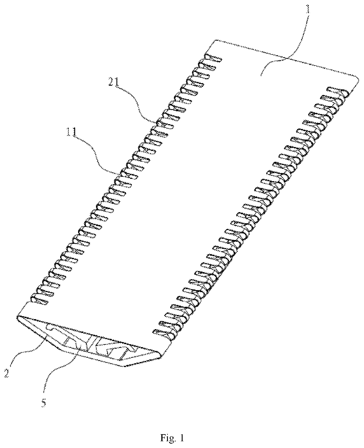
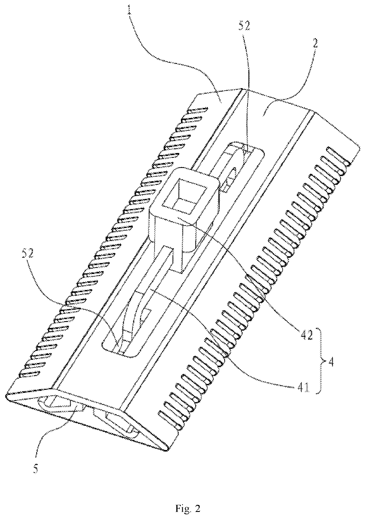
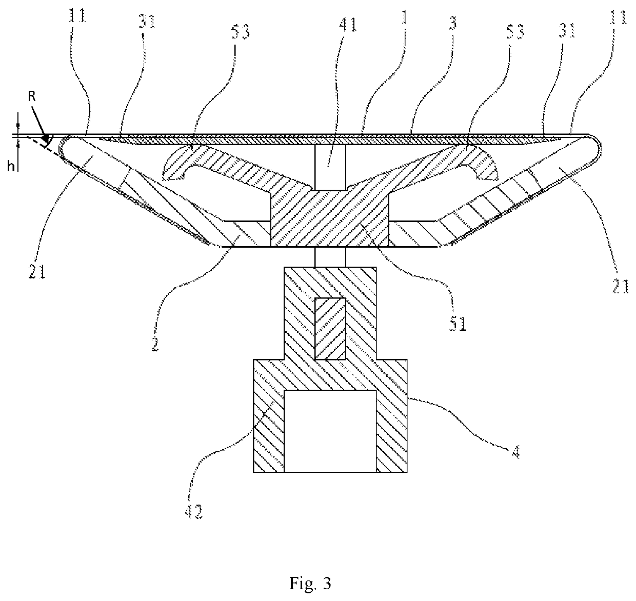
[0023]A reciprocating electric razor head as shown in FIGS. 1-4 is provided, including a fixed blade 1 and a fixed blade support 2 for supporting and fixing the fixed blade 1, wherein the fixed blade 1 is a flexible metal sheet having suppleness; the fixed blade support 2 is a rigid support, and the cross-section of the fixed blade support 2 is arcuate; the fixed blade 1 is supported by the edges on both left and right sides of the fixed blade support 2; under the action of a certain external force, both left and right ends of the fixed blade 1 are bent and tensioned downwardly along an arcuate outer side of the fixed blade support 2 to lie flat against the fixed blade support 2, and the fixed blade 1 is tightly fixed to a lateral face or a bottom face of the fixed blade support 2 by means of welding, riveting or gluing; the fixed blade 1 is provided with hair entrance holes 11 for body hair to enter, and an inner side of the fixed blade 1 is provided with a movable blade 3 capable ...

embodiment 2

[0034]Embodiment 2 as shown in FIGS. 6-8 is distinguished from Embodiment 1 in the following aspects: the movable blade pressing member 5 includes a supporting portion 54 supported on the fixed blade support 2, and includes a pair of elastic arms 55 for pushing the movable blade 3 upward, wherein each elastic arm 55 is provided with a curved portion 551 for pushing the movable blade 3 upward; the fixed blade support 2 is provided with two limit blocks 6, wherein each limit block 6 is provided with a strip-shaped slot 61 for mating with the movable blade support 41 and restricting the movable blade support 41 from moving horizontally; the strip-shaped slot 61 is used for guiding the movable blade 3 to move backward and forward in a reciprocating manner; moreover, the movable blade pressing member 5 is a sheet metal member, which ensures that the elastic arms 55 have good elasticity; as such, while the movable blade 3 is tightly appressed to the fixed blade 1, the movable blade 3 can ...


PUM


Abstract

A reciprocating electric razor head includes a fixed blade and a fixed blade support for supporting and fixing the fixed blade. The fixed blade is provided with hair entrance holes for body hair to enter, and an inner side of the fixed blade is provided with a movable blade capable of moving backward and forward in a reciprocating manner relative to the fixed blade to cut off the body hair inside the hair entrance holes, such that the fixed blade obtains a very flat cutting working face contacting the movable blade without the need for additional precision machining.

Description

CROSS REFERENCE TO RELATED APPLICATIONS[0001]The present application is a Continuation-In-Part Application of PCT Application No. PCT / CN2016 / 105186 filed on Nov. 9, 2016, which claims the benefit of Chinese Patent Application No. 201610889953.7 filed on Oct. 12, 2016. All the above are hereby incorporated by reference.TECHNICAL FIELD[0002]The present invention relates to a reciprocating electric razor head.BACKGROUND ART[0003]As for commercially available reciprocating electric razor heads, long body hair typically can't be cut clean in one time. Therefore, two sets of blades are required: one set of blades cut long hair first, and then, the other set of blades cut remaining short hair; alternatively, although long body hair can be cut off by these razor heads in one time, as limited by their structures, fixed blades or shaver caps can't be made to be fairly thin. Consequently, the hair remains after shaving, thus leading to unclean shaving.[0004]The present invention is created bas...

Claims


Application Information

Patent Timeline
Patent Type & Authority Patents(United States)
IPC IPC(8): B26B19/04B26B19/08B26B19/06B26B19/38
CPCB26B19/384B26B19/046B26B19/063B26B19/08B26B19/3846B26B19/042B26B19/06
Inventor WU, RANGPAN
Owner LITTLE STONE CERAMIC BLADE ZHONGSHAN CO LTD
Why Eureka
Try Eureka