
Information-presentation structure with smoothened impact-sensitive color-changed print area

a color change and information-presentation technology, applied in the field of information presentation, can solve the problems of difficult to determine the distance between the print area and the surface-zone boundary, and achieve the effects of reducing the delay of line-call review, easy visual determination, and high accuracy in determining the location of the print area

Active Publication Date: 2020-12-15
MEETIN RONALD J
View PDF71 Cites 0 Cited by
  • Summary
  • Abstract
  • Description
  • Claims
  • Application Information

AI Technical Summary

Benefits of technology

The patent describes a technology that allows for the detection and location of impacts on a surface, particularly in the context of sports equipment. The technology uses a special surface structure that is protected from damage and a method for detecting and measuring the pressure caused by the impact. This allows for accurate detection of the location and size of the impact, which can aid in determining the proper response to the impact. The technology can be used in a variety of sports equipment and activities. Overall, the technology provides a significant improvement over previous methods for detecting and measuring impacts on surfaces.

Problems solved by technology

The boundary of the surface zone and the perimeter of the print area commonly have irregularities that make it difficult to determine how close the print area comes to the surface-zone boundary.

Method used


Image

  • Information-presentation structure with smoothened impact-sensitive color-changed print area
  • Information-presentation structure with smoothened impact-sensitive color-changed print area
  • Information-presentation structure with smoothened impact-sensitive color-changed print area

Examples


embodiment 130

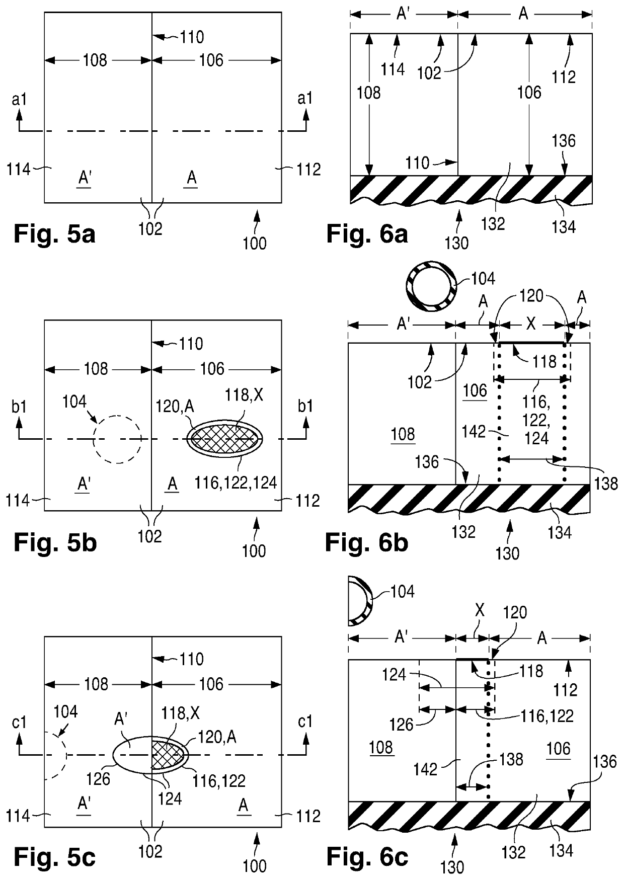
[0138]Referring to FIGS. 6a-6c (collectively “FIG. 6”), they illustrate a general embodiment 130 of OI structure 100 for which duration Δtdr of the changed state is automatic value Δtdrau absent externally caused adjustment. VC region 106 here consists only of the ISCC structure indicated here and later as item 132. In FIG. 6, surface 102 is flat and extends parallel to a plane generally tangent to Earth's surface. However, surface 102 can be significantly curved. Even when surface 102 is flat, it can extend at a significant angle to a plane generally tangent to Earth's surface as exemplified below in FIGS. 102a and 102b. Interface 110 between color regions 106 and 108 extends perpendicular to surface 102. See FIG. 6a. Interface 110 can be a flat surface or a curved surface which appears straight along a plane extending through regions 106 and 108 perpendicular to surface 102. Regions 106 and 108 lie on a substructure (or substrate) 134 usually consisting of insulating material at l...

embodiment 180

[0195]FIGS. 11a-11c (collectively “FIG. 11”) illustrate an embodiment 180 of OI structure 130 in which VC region 106 is again formed solely with ISCC structure 132. Region 106, and thus structure 132, here consists of a principal IS component 182 and a principal CC component 184 that meet at a flat principal light-transmission interface 186 extending parallel to SF zone 112 and interface 136. See FIG. 11a. IS component 182 extends between zone 112 and interface 186. CC component 184 extends between interfaces 186 and 136 and therefore between IS component 182 and substructure 134.

[0196]Light travels through IS component 182, usually transparent, from SF zone 112 to interface 186 and vice versa. Preferably, largely no light striking CC component 184 along interface 186 passes fully through component 184 to interface 136. All light striking component 184 along interface 186 is preferably absorbed and / or reflected by component 184 so that there is no substructure-reflected ARsb or XRsb...

embodiment 200

[0226]FIGS. 12a-12c (collectively “FIG. 12”) illustrate an embodiment 200 of OI structure 180 and thus of OI structure 130. CC component 184 in OI structure 200 consists of a principal electrode assembly 202, an optional principal near (first) auxiliary layer 204 extending between electrode assembly 202 and interface 186 to meet IS component 182, and an optional principal far (second) auxiliary layer 206 extending between assembly 202 and substructure 134. See FIG. 12a. The adjectives “near” and “far” are used to differentiate near auxiliary layer 204 and far auxiliary layer 206 relative to their distances from SF zone 112, far auxiliary layer 206 being farther from zone 112 than near auxiliary layer 204. “NA” and “FA” hereafter respectively mean near auxiliary and far auxiliary. Assembly 202, NA layer 204, and FA layer and 206 all usually extend parallel to one another and parallel to zone 112 and interface 136.

[0227]NA layer 204, if present, usually contains insulating material fo...


PUM

PropertyMeasurementUnit
thresholdaaaaaaaaaa
threshold impact criteriaaaaaaaaaaa
areaaaaaaaaaaa

Abstract

A variable-color region (106) extends to an exposed surface (102) at a zone (112) and normally appears along it as a principal color. The region responds to an object (104) impacting the zone sufficiently hard at an object-contact area (116) by providing an impact signal identifying a criteria-meeting area (1626) where threshold impact criteria are met. Responsive to the impact signal and possibly to supplemental impact criteria being met, a controller (1622) produces a representation of a print area (118) from a representation of the criteria-meeting area by smoothening its perimeter and provides an initiation signal designating a location in the zone for the print area such that it closely matches the object-contact area. An impact-dependent portion (138) of the region responds to the initiation signal and possibly to a tracking condition being met by temporarily appearing along the print area as changed color materially different from the principal color.

Description

CROSS-REFERENCES TO RELATED APPLICATIONS[0001]This application is a division of U.S. patent application (“USPA”) Ser. No. 15 / 597,050, filed 16 May 2017, now allowed, which is a continuation-in-part of each of the following twenty USPAs all filed 3 Nov. 2016 on inventions of Ronald J. Meetin: U.S. patent application Ser. No. 15 / 343,101, now allowed; U.S. patent application Ser. No. 15 / 343,113; U.S. patent application Ser. No. 15 / 343,115, now allowed; U.S. patent application Ser. No. 15 / 343,118, now allowed; U.S. patent application Ser. No. 15 / 343,121, now U.S. Pat. No. 9,789,381 B1; U.S. patent application Ser. No. 15 / 343,123, now allowed; U.S. patent application Ser. No. 15 / 343,125; U.S. patent application Ser. No. 15 / 343,127, now allowed; U.S. patent application Ser. No. 15 / 343,130, now allowed; U.S. patent application Ser. No. 15 / 343,131, now U.S. Pat. No. 9,855,485 B1; U.S. patent application Ser. No. 15 / 343,132, now allowed; U.S. patent application Ser. No. 15 / 343,133, now allow...

Claims


Application Information

Patent Timeline
Patent Type & Authority Patents(United States)
IPC IPC(8): A63B71/06G02F1/1333A63B71/00A63B24/00G02F1/155A63B102/02A63B102/18
CPCA63B71/0605G02F1/13338A63B71/00A63B71/0622G02F2001/133394A63B2220/806A63B2225/20A63B2220/807A63B2071/0611A63B2024/0037G02F2202/32A63B2225/74A63B2071/0625A63B2024/0043A63B2243/0037A63B2102/02A63B71/0608A63B2220/801A63B2243/007A63B2220/13A63B71/0619A63B2220/80A63B2071/0694A63B2102/18G02F1/155A63B2102/00G02F1/133394
Inventor MEETIN, RONALD J.
Owner MEETIN RONALD J
Learn More