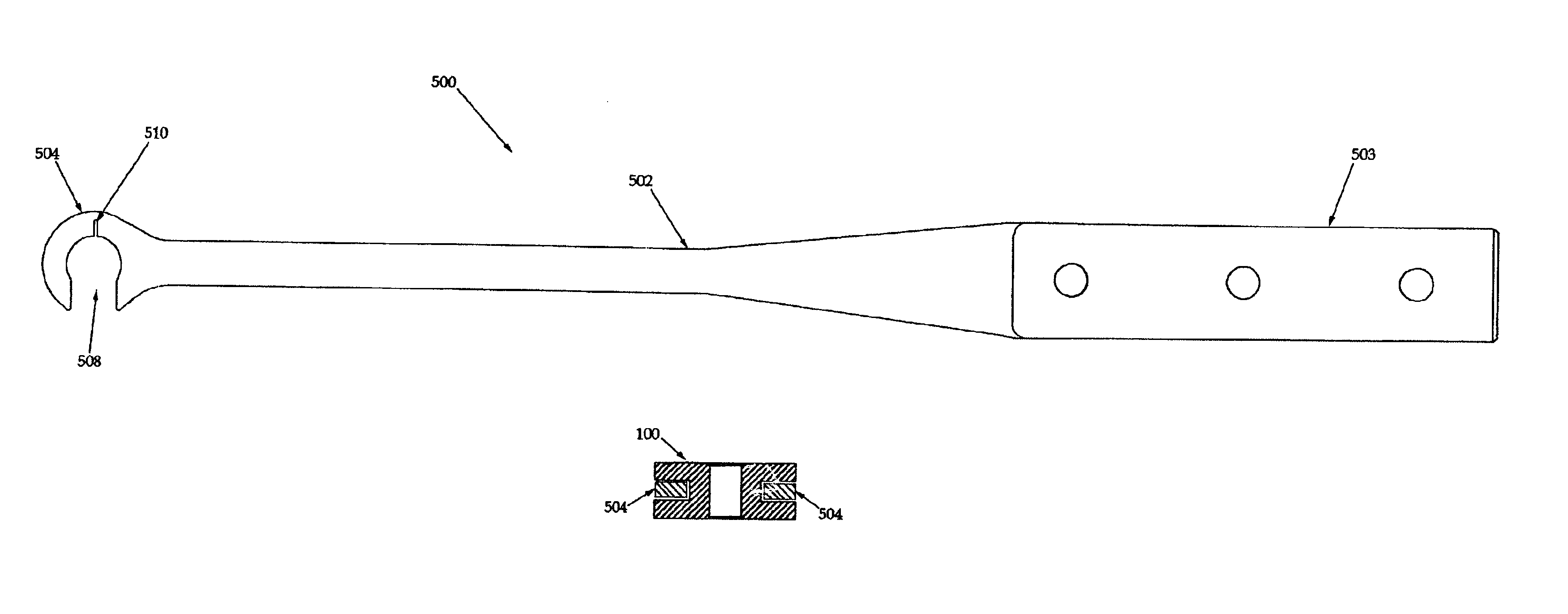
Insertion tool for use with trial intervertebral distraction spacers
a technology of intervertebral discs and insertion tools, which is applied in the field of scoliosis treatment, can solve the problems of neurological impairment and/or physiological disability, and the intervertebral discs of the spine are affected by the misalignment of the bones and the spine, so as to facilitate the application of the desired spreading force, distract the alignment of adjacent vertebral bones, and facilitate the effect of the sam
- Summary
- Abstract
- Description
- Claims
- Application Information
AI Technical Summary
Benefits of technology
Problems solved by technology
Method used
Image
Examples
first embodiment
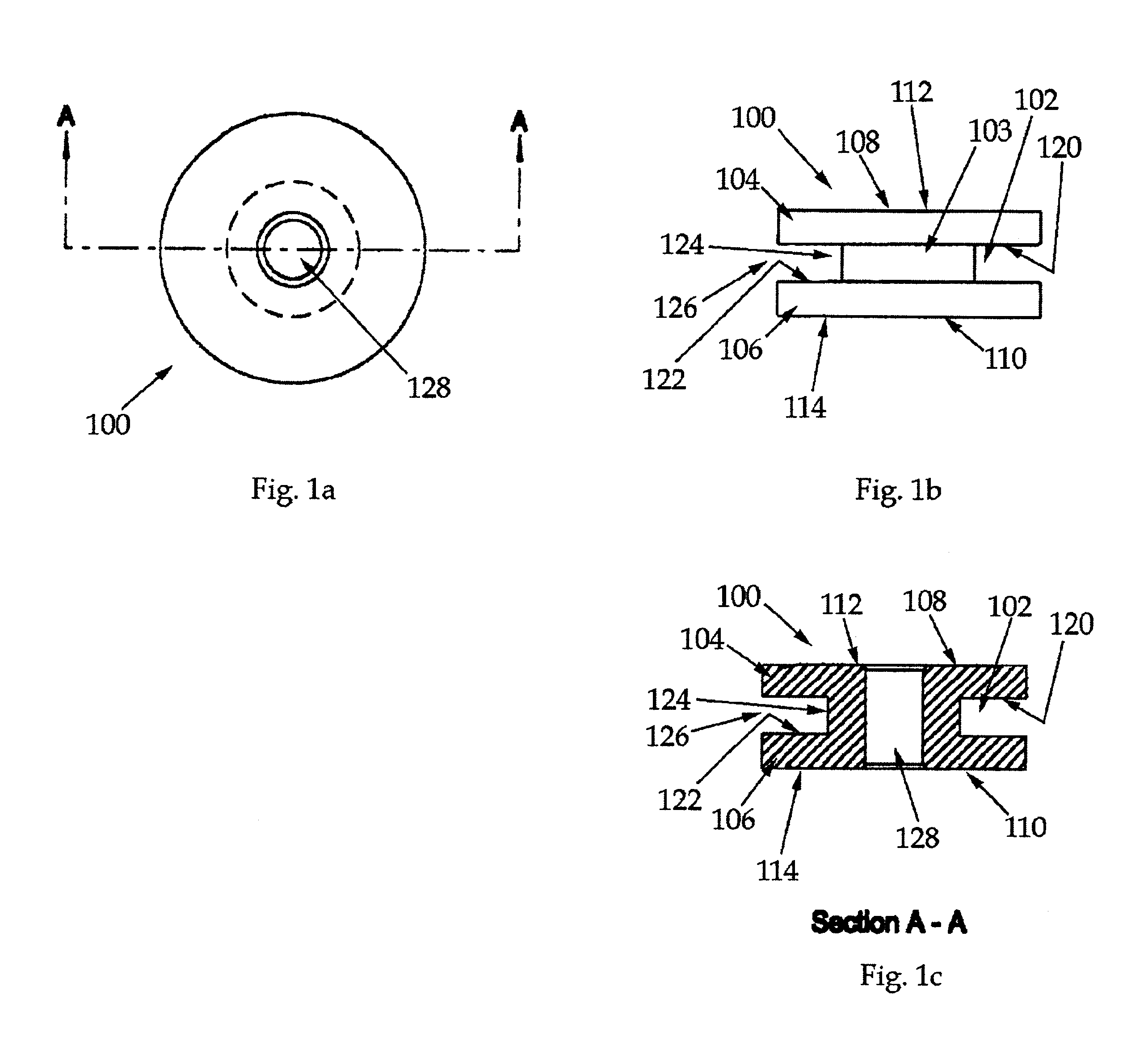
Referring now to FIGS. 1a-c, an intervertebral trial spacer 100 of the invention is illustrated in side, top and side cutaway views, respectively. The spacer 100 is a cylindrical disc with an annular groove 102 that forms a central trunk 103 and radial flanges 104,106 at each end of the trunk 102. In this embodiment, support portions 108,110 of the top and bottom surfaces 112,114 of the disc are parallel. Further in this embodiment, the walls 120,122 of the annular groove 102 are parallel, such that the floor 124 of the groove 102 is as wide as the opening 126 of the groove 102. Further in this embodiment, the spacer 100 has a central bore 128.
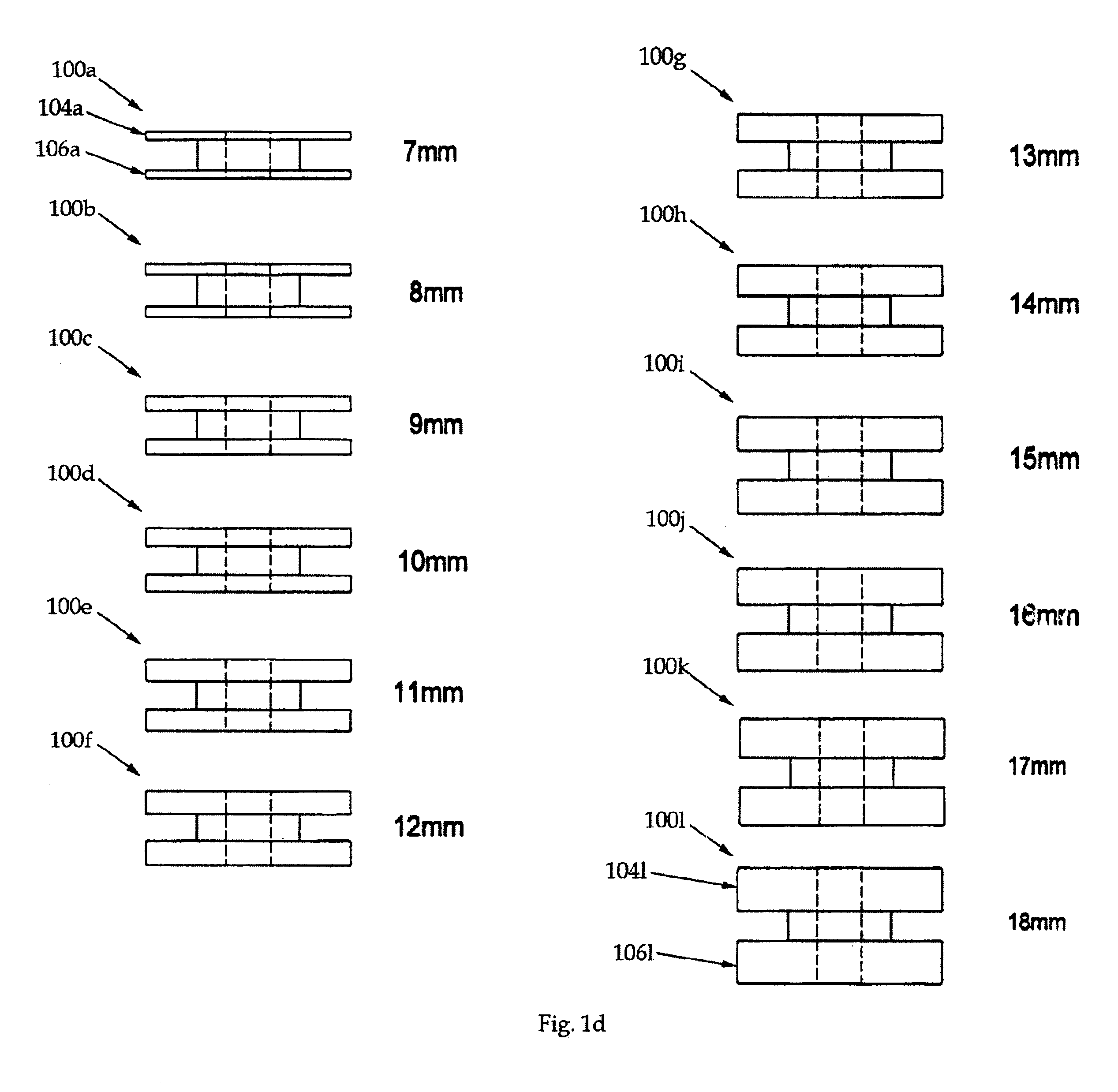
Referring now to FIG. 1d, a set of intervertebral spacers 100a-l of the invention are illustrated in a side view. Each spacer 100a-l is formed generally similarly to the intervertebral spacer 100 of FIGS. 1a-c, except that each spacer 100a-l has a predetermined depth (denoted by the preferred dimension identified adjacent each spacer) provided...
second embodiment
Referring now to FIGS. 2a-c, an intervertebral spacer 200 of the invention is illustrated in side, top and side cutaway views, respectively. Similarly to the spacer 100, the spacer 200 is a cylindrical disc with an annular groove 202 that forms a central trunk 203 and radial flanges 204,206 at each end of the trunk 202. However, in this embodiment, the flanges 204,206 are radially tapered in that support portions 208,210 of the top and bottom surfaces 212,214 of the disc are parallel, while an outer edge 216 of the top surface 212 is tapered toward an outer edge 218 of the bottom surface 214. Further in this embodiment, in contrast to the spacer 100, the walls 220,222 of the annular groove 202 are tapered toward one another with the increasing depth of the groove 202, such that the floor 224 of the groove 202 is more narrow than the opening 226 of the groove. Further in this embodiment, the spacer 200 has a central bore 228.
Referring now to FIG. 2d, a set of intervertebral spacers 2...
third embodiment
More particularly, the surgeon inserts the tapered trial spacers into the intervertebral space (presumably from the anterior, or anterio-lateral, approach) with the narrow edge of the trial spacer forming a wedge and sliding between the adjacent bones. By utilizing either a second or third embodiment of the spacer insertion tool, described more fully hereinafter with respect to FIGS. 7a-c and 8a-c respectively, the surgeon may turn the spacer around its axis within the intervertebral space to find the most appropriate rotational position (corresponding to the most desirable straightening effect on the spinal column). Stated alternatively, each of the tapered trial spacers has an overall wedge shape that generally corresponds to the pathological tapering of the adjacent bones that characterizes scoliosis. By rotating the wedge-shaped spacer after it has been placed between the adjacent bones, the overall disc alignment may be compensated, restoring appropriate anatomical status. It s...
PUM
 Abstract
Description
Claims
Application Information
 - R&D
- Intellectual Property
- Life Sciences
- Materials
- Tech Scout
- Unparalleled Data Quality
- Higher Quality Content
- 60% Fewer Hallucinations
Browse by: Latest US Patents, China's latest patents, Technical Efficacy Thesaurus, Application Domain, Technology Topic, Popular Technical Reports.
© 2025 PatSnap. All rights reserved.Legal|Privacy policy|Modern Slavery Act Transparency Statement|Sitemap|About US| Contact US: help@patsnap.com


