Plasma jet device

a technology of plasma jet and discharge arc, which is applied in the direction of plasma technique, chemical vapor deposition coating, coating, etc., can solve the problems of low treatment efficiency, easy formation of discharge arc, and inability to meet the requirements of certain applications, so as to improve the efficacy and expand the application of low-temperature plasma.

Inactive Publication Date: 2009-07-30
LU XINPEI +1
View PDF3 Cites 93 Cited by
  • Summary
  • Abstract
  • Description
  • Claims
  • Application Information

AI Technical Summary

Benefits of technology

[0045](10) The plasma jet generated by this present invention belongs to non-equilibrium low temperature plasma, which further expands the applications of low temperature plasma and improves its efficacy.

Problems solved by technology

If indirect treatment (remote exposure) is used, certain short lifetime active species, such as oxygen atom, charge particles may already disappear before reaching the object to be treated, which makes the efficiency of treatment much lower.
Because the electrode 3 and the grounding electrode 16 are contacted with the plasma jet 10 directly, this leads to discharge arc being formed easily when applying high voltage and is not safe for applications such as tooth cleaning, root canal disinfection, and acceleration of wound healing.
The main disadvantage of this device is that the electrode 3 is directly contacted with the plasma jet 10, which is also not safe in certain applications.
One of the disadvantages of this device is that the end of the electrode 3 is not covered by the dielectric material 5.
Therefore, the electrode 3 is directly contacting with plasma, which is not safe for certain applications.
However, the gas temperature of the plasma generated by most of these devices are relatively high, i.e., at least several hundred degrees, which limits their applications for the treatment of temperature sensitive objects.
One of the disadvantages of this device is that arc discharge between the electrode 3 and the grounding electrode 16 can occur directly under certain conditions, such as when the pulse width is larger than 10 μs.
As above mentioned, most of the conventional plasma jet devices have disadvantages.
Similar problems also exist for some recently patented plasma jet generating methods, apparatuses and systems.
These disadvantags limit the widely the use of the non-equilibrium plasmas in various applications.

Method used


Image

  • Plasma jet device
  • Plasma jet device
  • Plasma jet device

Examples


first embodiment

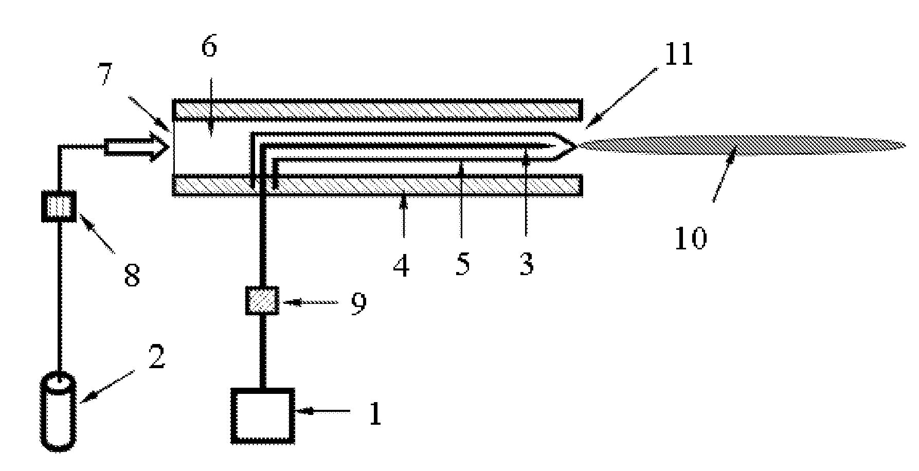
[0062]With reference to FIG. 5, a plasma jet device in accordance with the present invention will be explained. The device comprises a gas supply 2, a power supply 1, an electrode 3, a dielectric container 4 and a flow controller 8. The electrode 3, which is completely covered by the dielectric material 5, is inserted into the dielectric container 4 and connected to the power supply 1 through a power controller 9. The dielectric material 5 is in the form of a bent hollow tube with one end closed and another end opened, which is fixed inside the dielectric container 4. The top closed end of the dielectric material 5 has a pyramidal geometry. By controlling the flow controller 8, the flow rate of the working gas 6 injected into the dielectric container 4 through the gas inlet 7 is adjusted. The generated plasma jet 10 is ejected out of the plasma jet outlet 11.

second embodiment

[0063]FIG. 6 is a perspective view of the present invention. The device comprises a gas supply 2, a power supply 1, an electrode 3, a dielectric container 4, a flow controller 8, a nozzle 12, and a grounding electrode 16 covering outside of the nozzle 12. The electrode 3, which is completely covered by the dielectric material 5, is inserted into the dielectric container 4 and connected to the power supply 1 through a power controller 9. The dielectric material 5 is in form a hollow sheath with one end closed and another end opened, which is fixed inside the dielectric container 4 by the fixed-mount 13. There are two gas inlets 7 inside the fixed-mount 13, from the two gas inlets 7 the working gas 6 is injected into the dielectric container 4 uniformly. The plasma jet 10 is generated when the device operated.

[0064]The dielectric material 5 is a dielectric sheath with a spheriform end, where the open end is interposed fixedly into the fixed-mount 13. The electrode 3 is in the form of ...

third embodiment

[0065]FIG. 7 is a perspective view of the present invention with multiple electrodes inside the dielectric container, comprising a gas supply 2, a power supply 1, multiple electrodes 3, a dielectric container 4, and a nozzle 12. The multiple electrodes 3, which are completely covered by the dielectric material 5, are inserted into the dielectric container 4 and connected to the power supply 1 through a power controller 9. The dielectric material 5 is in the form of a tube with multiple rows of holes with one end closed and another end opened, which is fixed inside the dielectric container 4 by the fixed-mount 13. The flow rate of the working gas 6 injected into the dielectric container 4 from the gas inlets 7 is adjusted by the flow controller 8. The plasma jet 10 is generated when the device is operated.

[0066]FIGS. 8(a)-(b) illustrate cross-sectional views of a dielectric tube with six holes in two rows shown in the embodiment of FIG. 7, where the radial-section of the holes is a c...


PUM

PropertyMeasurementUnit
diameteraaaaaaaaaa
thicknessaaaaaaaaaa
thicknessaaaaaaaaaa

Abstract

A plasma jet device, comprising a dielectric container comprising a gas inlet and a plasma jet outlet, and an electrode. The electrode, which is completely covered by dielectric material, is inserted into the dielectric container and connected to the power supply. The dielectric material is in the form of a hollow tube with one end closed and another end opened. The power supply is connected to the electrode from the open end of the dielectric material. The dielectric material can also be a coated dielectric layer, which covers the electrode completely except one end for connecting to the power supply. A grounding electrode can be added downstream, outside the dielectric container or the nozzle. There also can be multiple electrodes inside the dielectric container arranged in a row or multiple rows, or in the shape of a circle or disk.

Description

CROSS-REFERENCE TO RELATED APPLICATIONS[0001]This application claims priority benefits to Chinese Patent Application No. 200810046795.4 filed Jan. 25, 2008, the contents of which, including any intervening amendments thereto, are incorporated herein by reference.BACKGROUND OF THE INVENTION[0002]1. Field of the Invention[0003]The present invention relates to a plasma jet device.[0004]2. Description of the Related Art[0005]Non-equilibrium plasmas have recently attracted a great amount of attention. Typically, plasma consists of ions, neutral species and electrons. In general, plasmas may be classified into thermal equilibrium and thermal non-equilibrium plasmas. Thermal equilibrium implies that the temperatures of all species including ions, neutral species, and electrons, are equal.[0006]Plasmas may also be classified into local thermal equilibrium (LTE) and non-LET plasmas. The term “local thermal equilibrium (LTE)” refers to a thermodynamic state where the temperatures of all the p...

Claims


Application Information

Patent Timeline
Patent Type & Authority Applications(United States)
IPC IPC(8): C23C16/513C23F1/02
CPCH05H1/24H05H1/2406H05H1/2418
Inventor LU, XINPEIPAN, YUAN
Owner LU XINPEI
Why Eureka
Try Eureka