Check valve

a check valve and valve body technology, applied in the field of check valves, can solve the problems of reducing the sealing effectiveness of the flapper, affecting the sealing effect of the flapper,

Active Publication Date: 2021-01-12
FMC TECH INC
View PDF20 Cites 1 Cited by
  • Summary
  • Abstract
  • Description
  • Claims
  • Application Information

AI Technical Summary

Benefits of technology

[0018]In accordance with another embodiment of the present disclosure, a check valve is provided which comprises a valve body which includes an inlet end, an outlet end, a flow bore that extends between the inlet and outlet ends, a cavity which intersects the flow bore, and an opening which is connected to the cavity, the flow bore comprising an inlet bore portion which extends between the inlet end and the cavity and an outlet bore portion which extends between the outlet end and the cavity; a body cap which is removably secured in the opening; a seat cartridge which is configured to be inserted through the opening and slidably received in the cavity, the seat cartridge defining a fluid pathway between the inlet bore portion and the outlet bore portion; and a flapper which is pivotable through the fluid pathway into a closed position to thereby prevent fluid from flowing from the outlet bore portion to the inlet bore portion through the seat cartridge.
[0035]Thus, it may be seen that the check valve of the present disclosure offers several advantages over prior art check valves. Rather than being press fit or screwed into the valve body during assembly of the check valve, the valve seat is formed on a seat cartridge which can be inserted into the cavity through the top opening in the valve body. As a result, field replacement of the valve seat can be easily accomplished by simply removing the old seat cartridge through the top opening and then inserting a new seat cartridge into the cavity.
[0036]Furthermore, since in some embodiments of the disclosure the floor of the seat cartridge is formed as a ramp that effectively extends from the valve seat to the bore of the seat cartridge which is contiguous with the outlet bore portion of the flow bore, fluid flow through the check valve will be less likely to cause significant erosion in the outlet bore portion.
[0037]Also, in certain embodiments of the check valve wherein the flapper includes a resilient coating on its sealing side, the flapper may be provided with a rigid stop ring which extends from the sealing side and limits the extent to which the resilient coating can be compressed against the valve seat when the flapper is in the closed position. As a result, the coating will not undergo plastic deformation when the pressure in the flow bore exceeds the compressive strength of the coating material, and the flapper will consequently continue to provide an effective seal.

Problems solved by technology

Also, the valve seat is typically press fit or screwed into the valve body during assembly of the check valve, which renders field replacement difficult.
In addition, when the sealing side of the flapper is coated with a resilient material, the coating can undergo plastic deformation and consequently reduce the sealing effectiveness of the flapper when the pressure in the flow bore exceeds the compressive strength of the coating material.
Furthermore, at high flow velocities the fluid being conveyed through the check valve can flow over the top of the flapper, which can lead to erosion of the pivot pin and the retainer ring.

Method used


Image

  • Check valve
  • Check valve
  • Check valve

Examples


Embodiment Construction

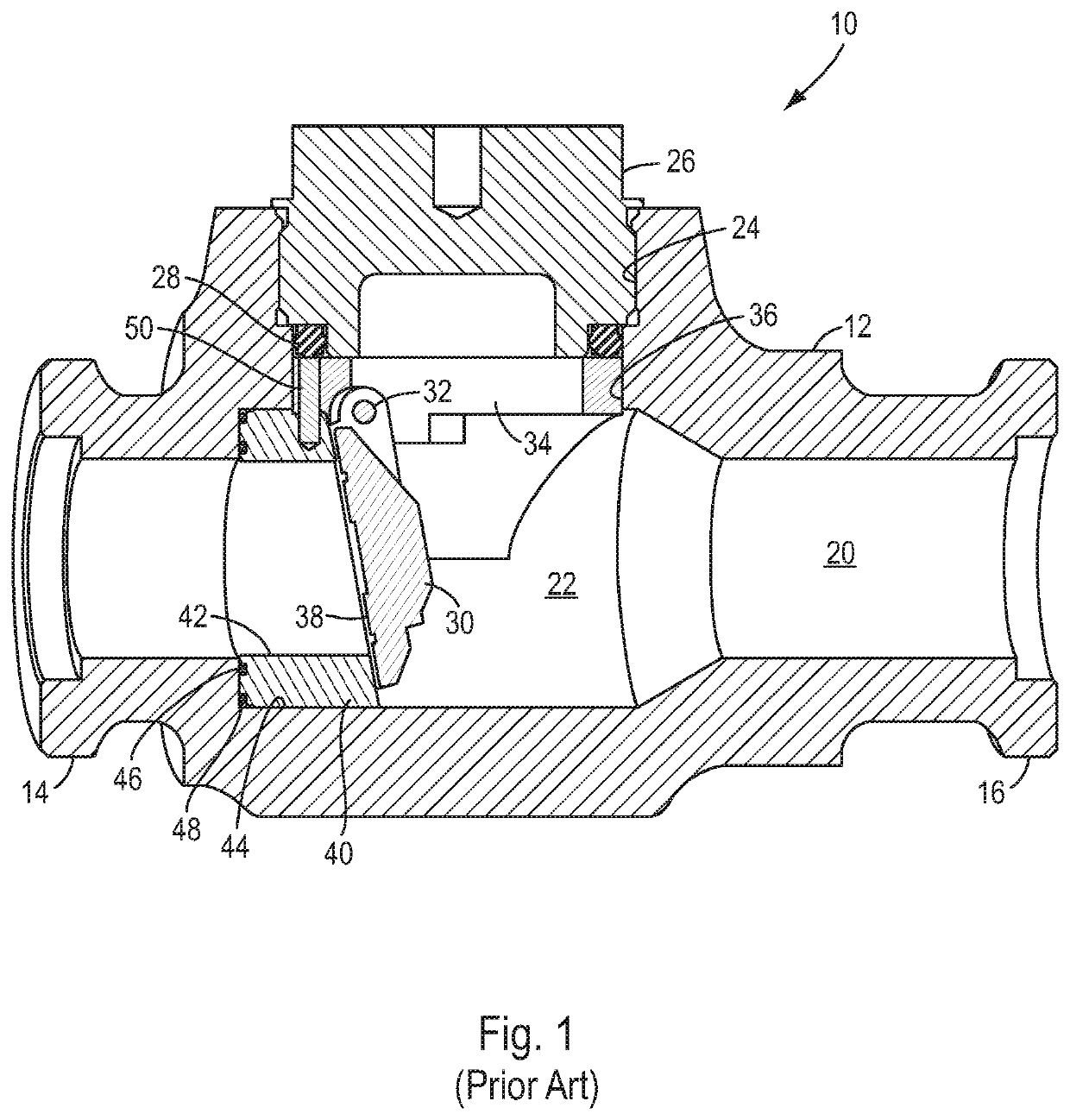
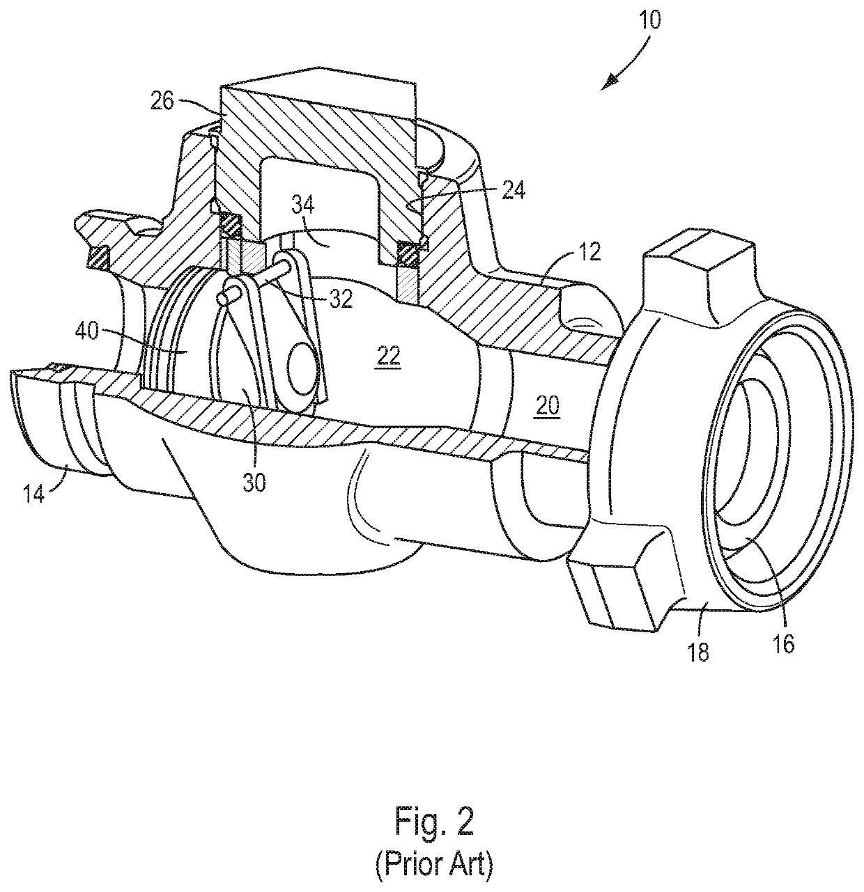
[0054]As context for the present disclosure, an example of a prior art check valve will first be described with reference to FIGS. 1 and 2. This prior art check valve, which is indicated generally by reference number 10, is shown to comprise a valve body 12 having first and second ends 14, 16 which are configured to be connected to flow pipes or other flow components (not shown) by suitable means, such wing unions 18 (only one of which is shown in FIG. 2) or other high pressure connections. The valve body 12 includes a flow bore 20 which extends between the first and second ends 14, 16, and a larger diameter cavity 22 which is formed coaxially within the flow bore. The cavity 22 is accessible through a top opening 24 in the valve body 12 which is closed by a removable body cap 26 that is threaded into the top opening and is sealed to the valve body by a ring seal 28.

[0055]The check valve 10 includes a flapper 30 which is pivotally connected by a pivot pin 32 to a retainer ring 34. T...


PUM


Abstract

A check valve includes a valve body having a flow bore which extends between the inlet and outlet ends of the body, a cavity which intersects the flow bore, and an opening which is connected to the cavity. A body cap is removably secured in the opening, and a seat cartridge is configured to fit through the opening and be slidably received in the cavity. The seat cartridge has an open first end which is aligned with the opening, a second end which is located opposite the first end, a chamber which extends between the first and second ends and defines an inner wall of the seat cartridge, a first bore which extends between the chamber and an inlet bore portion, a second bore which extends between the chamber and an outlet bore portion, and a valve seat which is formed on a portion of the inner wall that surrounds the first bore. A retainer ring is positioned in the valve body between the body cap and the first end of the seat cartridge, and a flapper is pivotally connected to the retainer ring and is pivotable through the chamber between a closed position in which the flapper is positioned against the valve seat and an open position in which the flapper is displaced from the valve seat.

Description

[0001]The present application is based upon and claims priority from U.S. Provisional Patent Application No. 62 / 340,063 filed on May 23, 2016.[0002]The present disclosure relates to a check valve which comprises a flapper for controlling fluid flow through the valve. More particularly, the present disclosure relates to a check valve in which the valve seat is formed on a seat cartridge that is oriented coaxially with, and is removable through, a top opening in the valve body. The present disclosure also relates to a check valve which comprises a resilient pivot pin retainer ring, or halo, that has the features and advantages discussed below.BACKGROUND OF THE INVENTION[0003]Certain prior art check valves have a flapper which is configured to engage a cylindrical valve seat that is positioned across a flow bore which extends longitudinally through the valve body. A larger diameter cavity is formed in the valve body coaxially with the flow bore, and the valve seat is often mounted in t...

Claims


Application Information

Patent Timeline
Patent Type & Authority Patents(United States)
IPC IPC(8): F16K15/03F16K27/02F16K15/00F16K1/46F16K1/42F16K1/44
CPCF16K15/03F16K1/42F16K1/44F16K1/46F16K15/00F16K27/0227
Inventor FINK, DANIEL R.
Owner FMC TECH INC
Why Eureka
Try Eureka