
Gradient coil unit for a magnetic resonance apparatus

a magnetic resonance apparatus and gradient coil technology, applied in the field of gradient coil units for magnetic resonance apparatuses, can solve the problems of vibration during operation, movement and/or bending of gradient coil units, large force acting on gradient coil units, etc., and achieve the effect of reducing electromagnetic interactions and peripheral nerve stimulation

Active Publication Date: 2021-02-02
SIEMENS HEALTHCARE GMBH
View PDF13 Cites 0 Cited by
  • Summary
  • Abstract
  • Description
  • Claims
  • Application Information

AI Technical Summary

Benefits of technology

[0006]An object of the invention is to provide a low-vibration gradient coil unit for generating magnetic field gradients with reduced peripheral nerve stimulation in the trunk of the body of the examination subject, and with reduced electromagnetic interaction outside the patient receiving region.

Problems solved by technology

The positioning of the gradient coil unit within the basic field magnet of the magnetic resonance scanner results in a large force acting on the gradient coil unit.
The force is associated with torque, which can result in movement and / or bending of the gradient coil unit.
This can result in vibrations during the operation of the gradient coil unit.
In addition to increased vibrations of the gradient coil unit, such specifications of the gradient coil unit are limited by interaction with the examination subject.

Method used


Image

  • Gradient coil unit for a magnetic resonance apparatus
  • Gradient coil unit for a magnetic resonance apparatus
  • Gradient coil unit for a magnetic resonance apparatus

Examples


Embodiment Construction

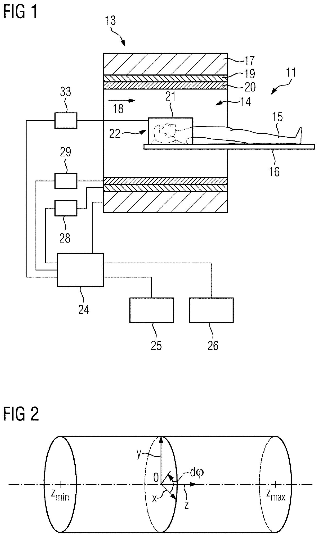
[0049]FIG. 1 is a schematic depiction of a magnetic resonance apparatus 11 according to the invention. The magnetic resonance apparatus 11 has a scanner 13 with a basic field magnet 17 that generates a strong and constant basic magnetic field 18. In addition, the magnetic resonance scanner 13 has a cylindrical patient receiving region 14 for receiving a patient 15. The patient receiving region 14 is enclosed circumferentially by the scanner 13. The patient 15 can be moved by a patient support device 16 into the patient receiving region 14. To this end, the patient support device 16 has a patient table that is movable within the scanner 13.

[0050]The scanner 13 can optionally have a main gradient coil unit 19 used for spatial encoding during imaging. The main gradient coil unit 19 is activated by a main gradient controller 28. The main gradient coil unit 19 is typically used in the absence of a gradient coil 21 unit according to the invention. The gradient coil unit 21 according to th...


PUM

PropertyMeasurementUnit
magnetic fieldaaaaaaaaaa
currentsaaaaaaaaaa

Abstract

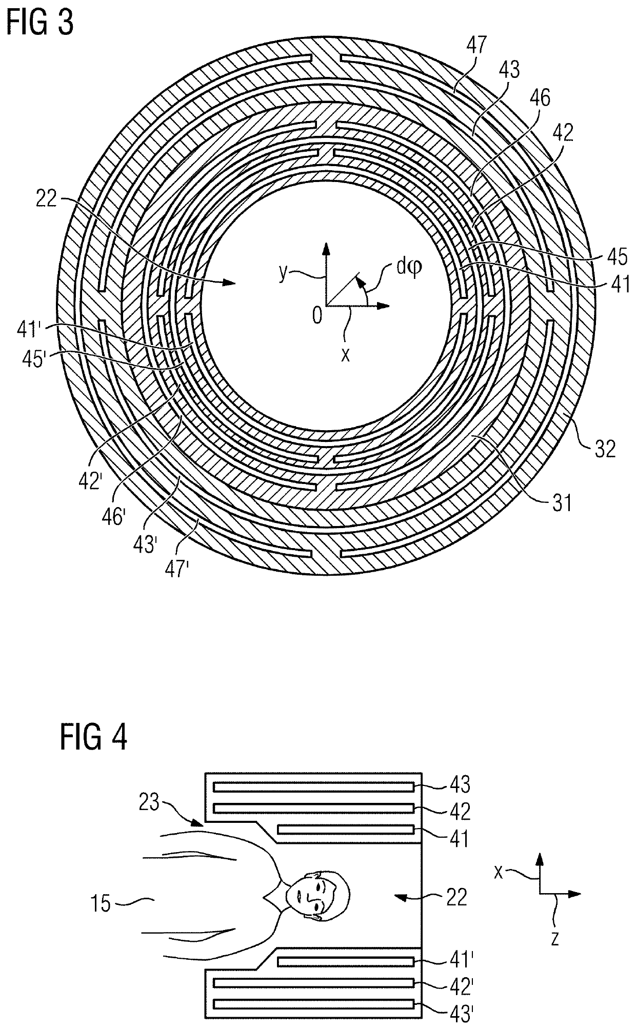
The invention relates to a gradient coil unit comprising a first conductor structure arranged on a surface of a first cylinder with the first radius, a second conductor structure arranged on a surface of a second cylinder with the second radius and a third conductor structure arranged on a surface of a third cylinder with the third radius, wherein the first radius is smaller than the second radius and the second radius is smaller than the third radius.

Description

BACKGROUND OF THE INVENTIONField of the Invention[0001]The invention concerns a gradient coil unit for a magnetic resonance apparatus, the gradient coil unit having a first conductor structure, a second conductor structure, a third conductor structure. The invention also concerns a magnetic resonance apparatus that includes such a gradient coil unit.Description of the Prior Art[0002]In a magnetic resonance scanner, the body of an examination subject, in particular a patient, is typically exposed, with the use of a basic field magnet, to a relatively basic main magnetic field, for example 1.5, 3 or 7 tesla, in a patient receiving region of the scanner. In addition, gradient pulses are activated by a gradient coil unit. Radio-frequency pulses (RF pulses), in particular excitation pulses, are emitted via a radio-frequency antenna unit with suitable antennas. Nuclear spins of certain atoms that are resonantly excited by these RF pulses are tilted by a defined flip angle relative to the ...

Claims


Application Information

Patent Timeline
Patent Type & Authority Patents(United States)
IPC IPC(8): G03G15/16G01R33/385
CPCG01R33/3858A61B5/055G01R33/4215G01R33/3854G01R33/385
Inventor DIETZ, PETER
Owner SIEMENS HEALTHCARE GMBH
Learn More