
Systems and methods for steam ring heating for bearing removal from shaft

a technology of steam ring heating and bearings, which is applied in the direction of bearing rigid support, manufacturing tools, mechanical equipment, etc., can solve the problems of both shafts and bearings being damaged, and achieve the effect of preventing relative movement between steam ring and sha

Active Publication Date: 2021-02-16
SAUDI ARABIAN OIL CO
View PDF15 Cites 0 Cited by
  • Summary
  • Abstract
  • Description
  • Claims
  • Application Information

AI Technical Summary

Benefits of technology

The steam ring system effectively reduces the force needed to remove bearings from shafts, minimizing damage and risk of fire, while being easily deployable in industrial settings with a readily available steam source.

Problems solved by technology

However, such methods can damage both the shaft and the bearing.

Method used


Image

  • Systems and methods for steam ring heating for bearing removal from shaft
  • Systems and methods for steam ring heating for bearing removal from shaft
  • Systems and methods for steam ring heating for bearing removal from shaft

Examples


Embodiment Construction

[0015]The disclosure refers to particular features, including process or method steps. Those of skill in the art understand that the disclosure is not limited to or by the description of embodiments given in the specification. The subject matter of this disclosure is not restricted except only in the spirit of the specification and appended Claims.

[0016]Those of skill in the art also understand that the terminology used for describing particular embodiments does not limit the scope or breadth of the embodiments of the disclosure. In interpreting the specification and appended Claims, all terms should be interpreted in the broadest possible manner consistent with the context of each term. All technical and scientific terms used in the specification and appended Claims have the same meaning as commonly understood by one of ordinary skill in the art to which this disclosure belongs unless defined otherwise.

[0017]As used in the Specification and appended Claims, the singular forms “a”, ...


PUM


Abstract

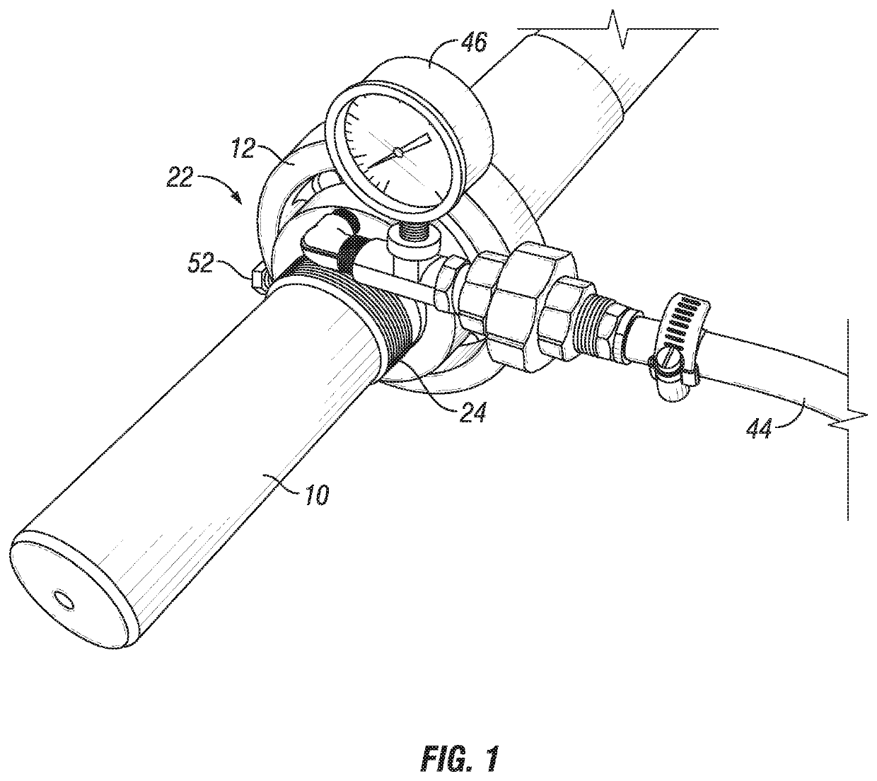
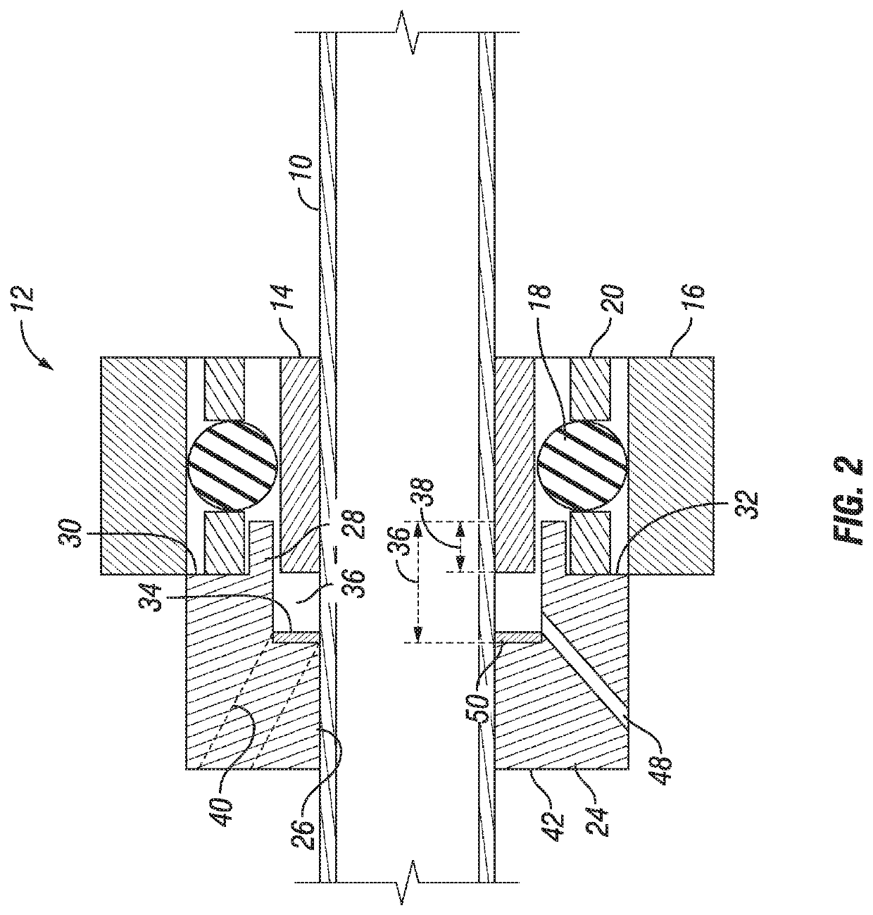
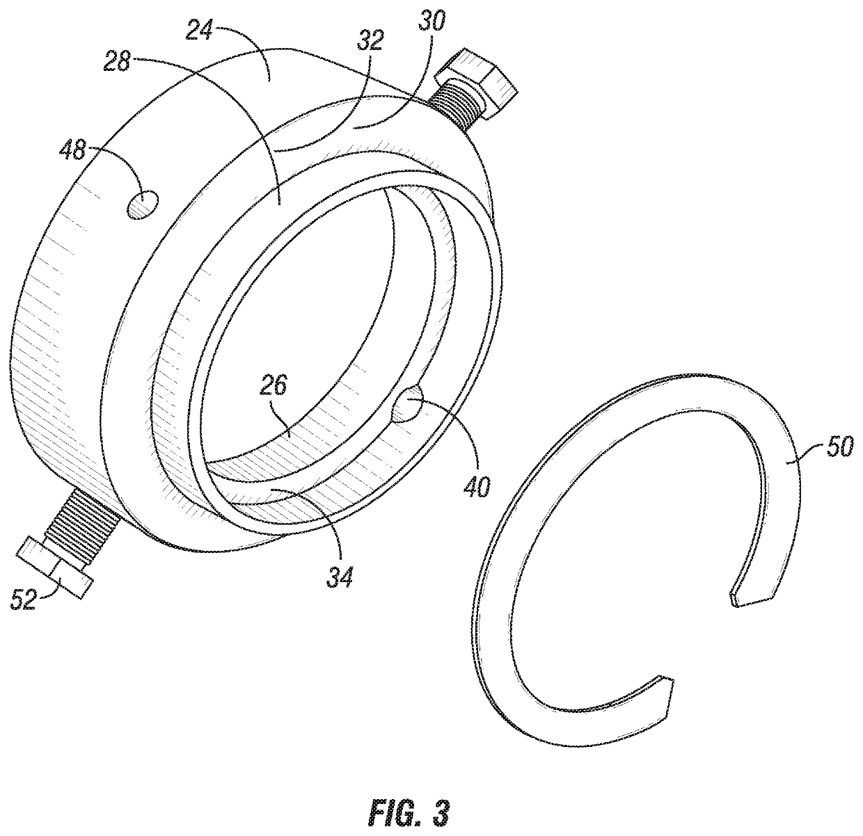
Systems and methods for removing a bearing assembly from a shaft include a steam ring, the steam ring being a ring shaped member. The steam ring has an inner bore sized to circumscribe the shaft. A lip ring extends from a first end face of the steam ring and has an inner diameter length that is greater than an outer diameter length. A steam inlet port extends through a sidewall of the steam ring. A steam outlet port extends through the sidewall of the steam ring at a location spaced apart from the steam inlet port.

Description

BACKGROUND OF THE DISCLOSURE1. Field of the Disclosure[0001]The present disclosure relates to bearing assemblies, and more specifically, the disclosure relates to reducing the magnitude of force required for removing a bearing from a shaft.2. Description of the Related Art[0002]Rotating shafts in industrial facilities can be fit with bearings to allow for relative rotation between the shaft and related equipment. The bearing can be interference fit on the shaft so that the bearing inner race remains static relative to the shaft, while the outer race of the bearing rotates. If the bearing needs to be removed from the shaft for maintenance or replacement, it can be a challenge to remove the bearing without damaging the bearing or shaft. In addition to the tight fit of the bearing on the shaft, dirt and debris may have built up over time on the shaft or in the bearing that inhibits the removal of the bearing from the shaft.SUMMARY OF THE DISCLOSURE[0003]Current systems for removing a b...

Claims


Application Information

Patent Timeline
Patent Type & Authority Patents(United States)
IPC IPC(8): B25B27/06F16C35/06F16C35/078F16C35/063F16C19/06
CPCB25B27/064F16C35/062F16C35/078F16C19/06F16C35/063F16C2226/12F16C2226/14F16C2300/02
Inventor AL-ZAHRANI, RAKAN SAEED
Owner SAUDI ARABIAN OIL CO
Learn More