
Lid with ventilation system

a ventilation system and lid technology, applied in the field of lids, can solve the problems of liquid leaving the container, the lid cannot be stored space-savingly, and the labyrinth seal does not always prevent liquid from flowing past the labyrinth seal, so as to achieve the effect of reliably preventing liquid from flowing out of the container

Active Publication Date: 2021-02-16
EMM HLDG BV
View PDF12 Cites 2 Cited by
  • Summary
  • Abstract
  • Description
  • Claims
  • Application Information

AI Technical Summary

Benefits of technology

[0005]The embodiments disclosed herein provide a container with a ventilation system for venting the container which reliably prevents liquid from flowing out of the container during use.
[0007]The ventilation system provides a reliable venting of the container without risk of liquid flowing out through the ventilation system, as the ventilation system does not require opening or closing during use of the liquid spraying device. The tube serves as an extension of the ventilation hole into the inside of the container and is sealed at a proximal end by the valve in a liquid tight manner. The valve prevents liquid from flowing out of the container into the ventilation system during use, i.e. during the refilling process, as the spraying device is inverted from the filling position to the spraying position, and during the spraying process. In addition, it is possible to easily refill the container by removing the lid from the container together with the ventilation system.

Problems solved by technology

However, opening and closing the vent opening at the correct point in time is cumbersome and may cause problems, such as liquid leaving the container, if the vent opening is not closed correctly.
However, the labyrinth seal does not always prevent liquid from flowing past the labyrinth seal, particularly when the container is inverted.
Moreover, the labyrinth seal protrudes from the lid, such that the lid cannot be stored in a space-saving manner.

Method used


Image

  • Lid with ventilation system
  • Lid with ventilation system
  • Lid with ventilation system

Examples


Embodiment Construction

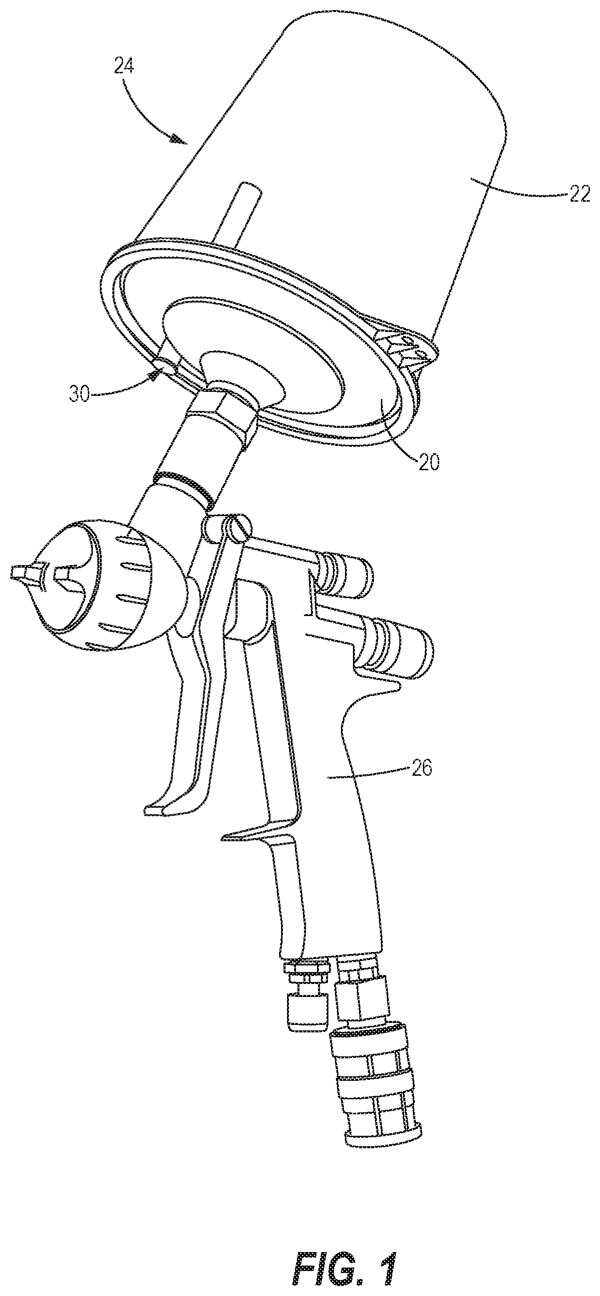
[0019]FIG. 1 shows a lid 20 according to the present disclosure connected to a container 22 to form an enclosed receptacle 24 for holding a liquid to be dispensed. The lid 20 and container 22 are inverted and attached to a gravity feed liquid spraying device 26. The lid 20 includes a ventilation system 30 for selectively permitting ambient air to flow into the receptacle 24.

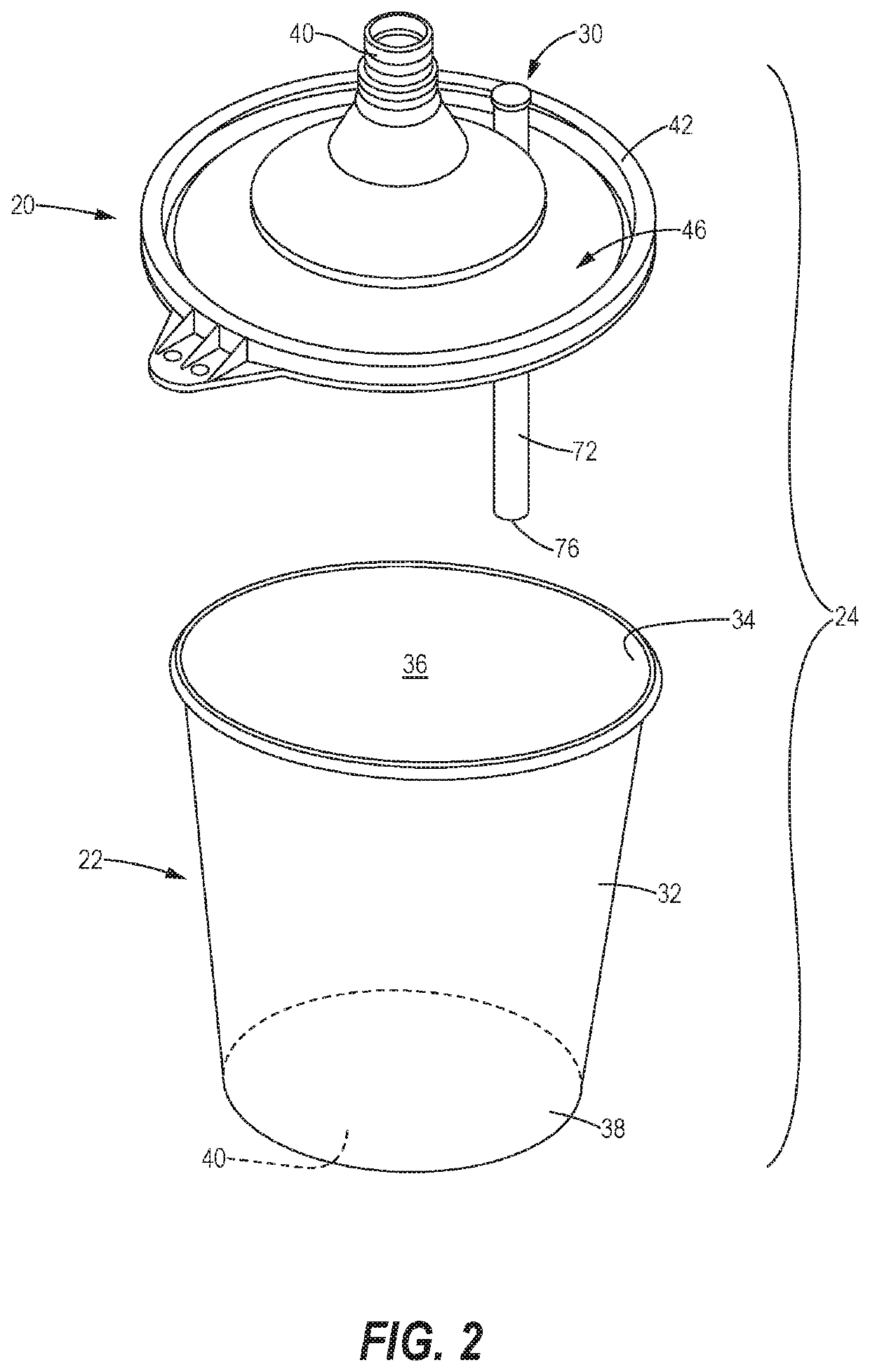
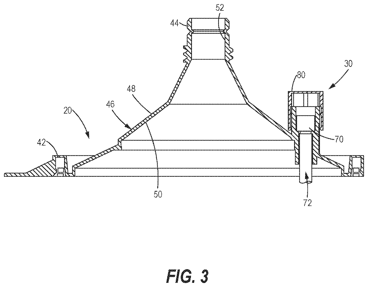
[0020]FIGS. 2 and 3 illustrate the lid 20 and container 22 in greater detail. The container 22 includes a side wall 32 having an open upper end 34, defining an opening into an interior 36 of the container 22, and a bottom end 38 closed off by a bottom wall 40. The lid 20 includes an outer rim 42, sized to sealably engage the upper end 34 of the container 22, and an adapter 44 for releasably engaging the liquid spraying device 26. A lid body 46 extends between the outer rim 42 and the adapter 44 to define a lid exterior surface 48, facing away from the container 22, and a lid interior surface 50, facing toward the...


PUM


Abstract

A lid, for attachment to a container holding a liquid for use with a liquid spraying device, a vent duct defining a vent conduit extending through a lid body from a duct inlet end to a duct outlet end. A valve is disposed in the vent duct and is configured to permit air flow in a first direction, from the duct inlet end to the duct outlet end, while preventing liquid flow in a second direction opposite the first direction. A cap extends over the duct inlet end, the cap including a cap interior surface defining an interior air chamber, communicating with the vent conduit, and at least a first passage, communicating between the interior air chamber and a first cap inlet. A tube is coupled to the duct outlet end and has a tube outlet end fluidly communicating with an interior of the container.

Description

BACKGROUNDTechnical Field[0001]The present disclosure generally relates to a lid for a container to be connected to a liquid spraying device, and in particular a lid with a ventilation system for venting the container.Description of the Related Art[0002]Liquid spraying devices may use different techniques to transport liquid from a container to a spraying mechanism. In general, suction feed liquid spraying devices and gravity feed liquid spraying devices are known. For suction feed liquid spraying devices, the container is generally located below the spraying mechanism and the liquid is sucked up from the container and to the spraying mechanism using negative pressure. In the case of gravity feed liquid spraying devices, the container is generally located above the spraying mechanism and the liquid can flow from the container towards the spraying mechanism under gravity. Regardless of the type of liquid spraying device, it is desirable to have an uninterrupted flow of liquid from th...

Claims


Application Information

Patent Timeline
Patent Type & Authority Patents(United States)
IPC IPC(8): B65D51/16B05B7/24B05B15/63
CPCB65D51/165B05B7/247B05B7/2478B05B15/63B05B7/2408
Inventor SMITSHOEK, TOM
Owner EMM HLDG BV
Learn More