Radiation irradiating apparatus

a technology main body, which is applied in the field of radiation irradiation apparatus, can solve the problems of exposing switch dropping and breaking, misplaced and unusable exposing switch, etc., and achieves the effect of easy attaching and detachabl

Active Publication Date: 2021-03-09
FUJIFILM CORP
View PDF24 Cites 1 Cited by
  • Summary
  • Abstract
  • Description
  • Claims
  • Application Information

AI Technical Summary

Benefits of technology

[0008]Considering the aforementioned issues, the present disclosure provides a radiation irradiating apparatus that enables an exposing switch to be integrally carried together with a radiation irradiating apparatus main body having a radiation generator and that enables the exposing switch to be easily attachable / detachable with respect to the radiation irradiating apparatus main body.
[0024]According to the radiation irradiation apparatus of the present disclosure, the radiation generator and the switch are attachable and detachable to and from each other via a surface of a portion of each of the housings thereof, which enables the switch to be integrally carried together with the radiation generator and enables the switch to be easily attachable and detachable with respect to the radiation generator. Moreover, due to the switch being attached with respect to the radiation generator via the surfaces, it is possible to attach the switch in a stable state, compared to the switch attached by being hooked on a hook mechanism or the like.

Problems solved by technology

It is however not possible to integrally carry the radiation irradiating apparatus main body and the exposing switch when, as described above, the exposing switch is provided as an independent unit separately from the radiation irradiating apparatus main body.
Thus, there is the possibility of the exposing switch being misplaced and unusable at an actual photographing location.
In addition, there is the possibility of the exposing switch being dropped and broken during carrying of the radiation irradiating apparatus and during setting of the radiation irradiating apparatus at an actual location.
It may be considered to, for example, dispose a hook mechanism or the like on the radiation irradiating apparatus main body and to hook the exposing switch on the hook mechanism and carry the exposing switch together with the radiation irradiating apparatus main body; however, there is still the possibility of the exposing switch being dropped and broken as a result of a trouble in hooking the exposing switch on the hook mechanism or as a result of a failure in hooking thereof.

Method used


Image

  • Radiation irradiating apparatus
  • Radiation irradiating apparatus
  • Radiation irradiating apparatus

Examples


Embodiment Construction

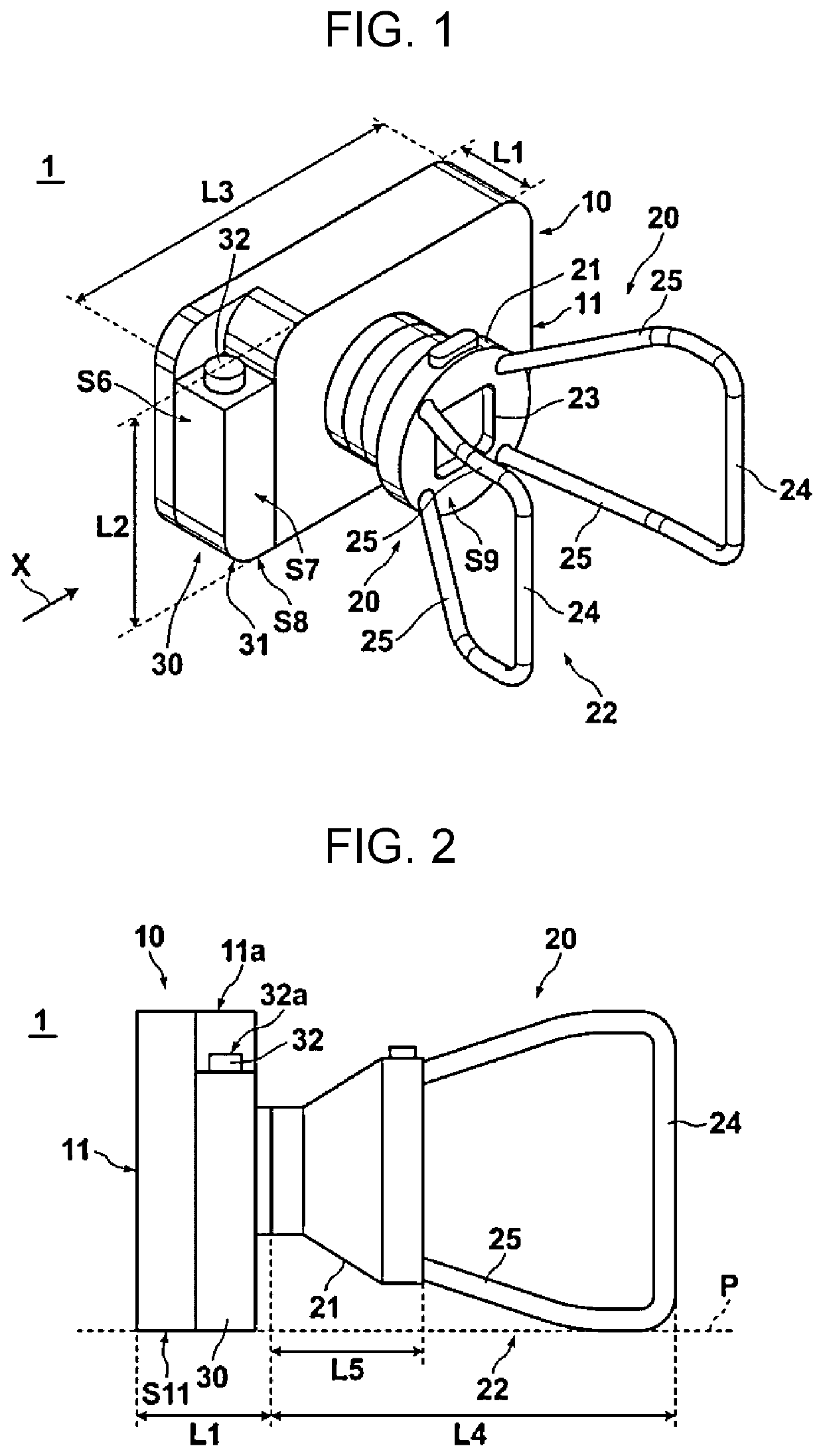
[0040]Hereinafter, an embodiment of the radiation irradiating apparatus according to the present disclosure will be described in detail with reference to the drawings. The radiation irradiating apparatus according of the present embodiment is a carriable radiation irradiating apparatus for use mainly at home or in disaster areas and the like. FIG. 1 is a perspective view illustrating an external configuration of a radiation irradiating apparatus 1 of the present embodiment. FIG. 2 is an external side view of the radiation irradiating apparatus 1 illustrated in FIG. 1 as viewed in the arrow X direction.

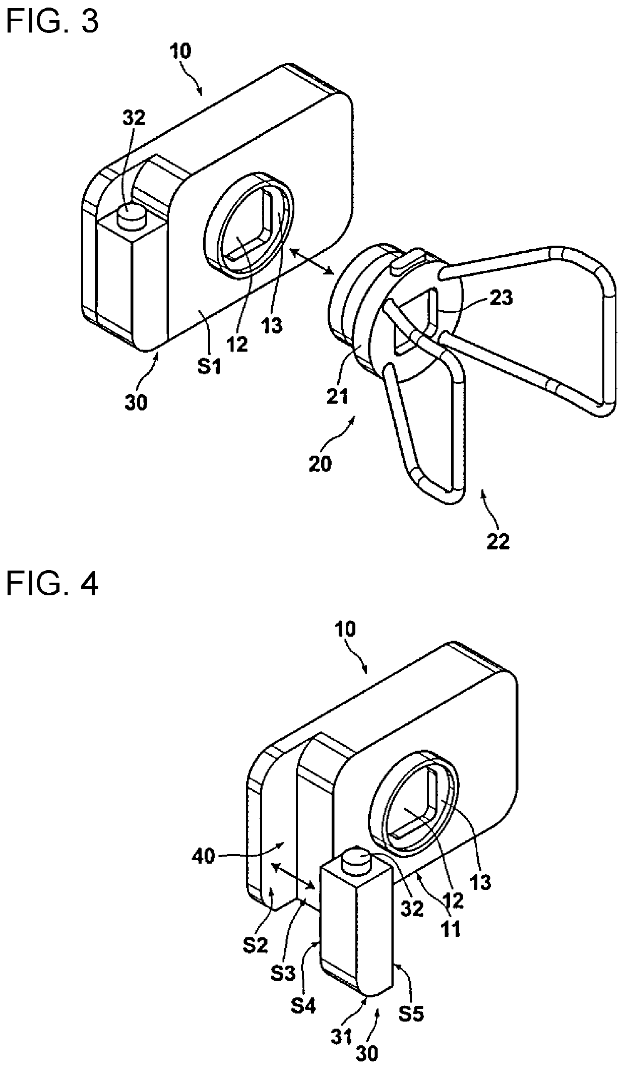
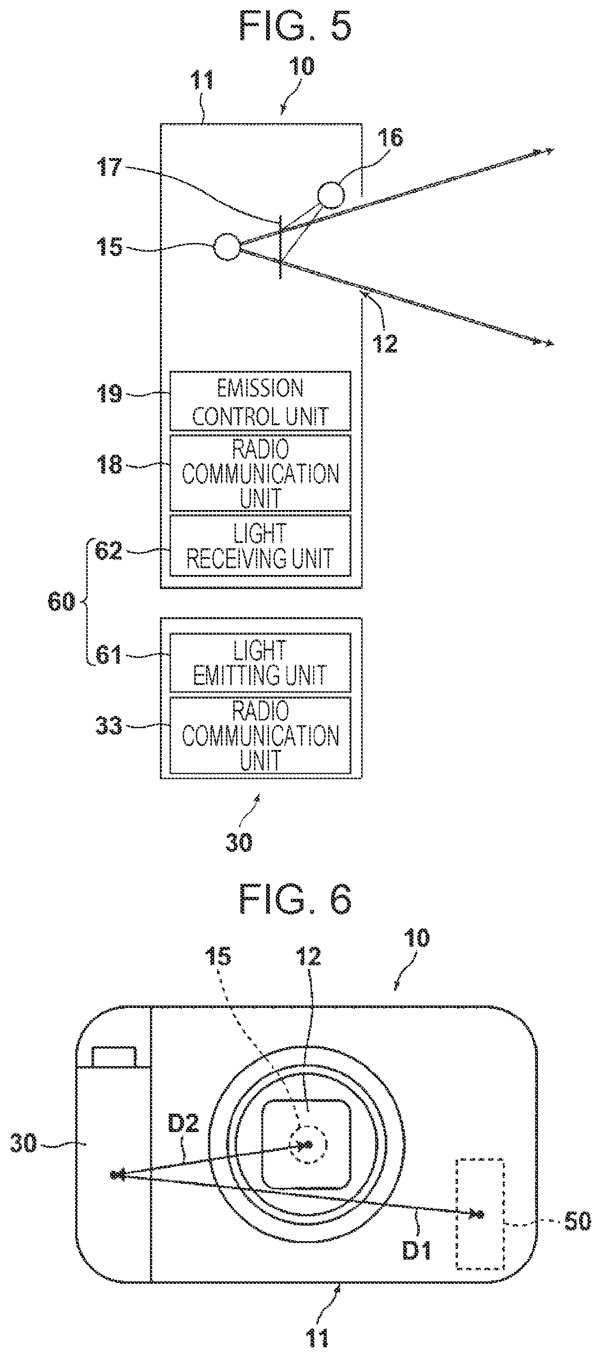
[0041]As illustrated in FIG. 1, the radiation irradiating apparatus 1 of the present embodiment includes a radiation generator 10, a detachable portion 20, and an exposing switch 30 (corresponding to the switch of the present disclosure).

[0042]The radiation generator 10 includes a radiation source 15, such as an X-ray tube, that generates radiation. The radiation generator 10 emits rad...


PUM


Abstract

A radiation irradiating apparatus includes a radiation generator that generates radiation and a switch that controls emission of the radiation from the radiation generator. The radiation generator and the switch are constituted by separate housings. The radiation generator and the switch are attachable and detachable to and from each other via a surface of a portion of each of the housings thereof.

Description

CROSS-REFERENCE TO RELATED APPLICATION[0001]The present application is a Continuation of PCT International Application No. PCT / JP2017 / 038362 filed on Oct. 24, 2017, which claims priority under 35 U.S.C. § 119(a) to Japanese Patent Application No. 2017-037297 filed on Feb. 28, 2017. Each of the above applications is hereby expressly incorporated by reference, in its entirety, into the present application.BACKGROUNDTechnical Field[0002]The present disclosure relates to a radiation irradiating apparatus for use in radiography and relates, in particular, to a portable radiation irradiating apparatus.Description of the Related Art[0003]Various carriable (portable) radiation irradiating apparatuses for use at home or in disaster areas and the like have been proposed.[0004]Such a carriable radiation irradiating apparatus includes an exposing switch for controlling exposure of radiation. In general, an exposing switch is configured, as an independent unit, separately from a radiation irradi...

Claims


Application Information

Patent Timeline
Patent Type & Authority Patents(United States)
IPC IPC(8): G21K5/00H05G1/10A61B6/00H05G1/02H05G1/56
CPCA61B6/54A61B6/4405H05G1/02H05G1/10H05G1/56A61B6/40
Inventor SATO, MASARUNAKAMURA, KENJIKAWAHARA, MISAKINARIYUKI, FUMITOOGURA, RYOSUKENAKASHIMA, TOMOAKI
Owner FUJIFILM CORP
Why Eureka
Try Eureka