Honeycomb filter

a honeycomb filter and filter body technology, applied in the field of honeycomb filters, can solve the problems of easy falling of plugging portions from the end of the cell, affecting the effect of the filter, so as to achieve the effect of preventing falling or breaking and effective preventing falling

Active Publication Date: 2021-03-09
NGK INSULATORS LTD
View PDF4 Cites 6 Cited by
  • Summary
  • Abstract
  • Description
  • Claims
  • Application Information

AI Technical Summary

Benefits of technology

[0009]In view of the above circumstances, the present invention has been made. The present invention is intended to provide a honeycomb filter capable of effectively preventing plugging portions disposed to plug open ends of cells from falling or breaking.
[0023]The honeycomb filter of the present invention can effectively prevent plugging portions disposed to plug open ends of cells from falling or breaking. In other words, by setting X represented by Formula (1) to satisfy the relation of Formula (2), a porous body forming the partition walls can satisfactory engage with a porous body forming the plugging portions on the interface therebetween, and the plugging portions can be effectively prevented from falling. Formula (1) includes, as a variable, the occupancy N1(%) of partition walls relative to the area of a cross section orthogonal to the cell extending direction of a honeycomb structure, and thus plugging portions can be prevented from falling or breaking depending on the cell structure of a honeycomb structure.

Problems solved by technology

Conventional honeycomb filters have a problem of easy falling of plugging portions from ends of cells.
Even when plugging portions do not fall, the plugging portions may break due to various stresses applied to a honeycomb filter, unfortunately.
When such an ash cleaning is conducted, the pressure of a high-pressure air may cause plugging portions to fall from end portions of cells or may cause plugging portions to break.
Also during such canning, plugging portions may fall from ends of cells or plugging portions may break.
In addition, a honeycomb filter is used in an environment where the honeycomb filter is exposed to exhaust gas at high temperature, thus the honeycomb filter inevitably has a temperature gradient, and a thermal stress is generated.
In such a condition, the stress is likely to concentrate on the boundary between partition walls provided to surround cells and plugging portions disposed on end portions of the cells, and the plugging portions may fall from end portions of the cells or plugging portions may break.

Method used


Image

  • Honeycomb filter
  • Honeycomb filter
  • Honeycomb filter

Examples


example 1

[0059]To 100 parts by mass of a cordierite forming raw material, 5 parts by mass of a pore former, 40 parts by mass of a dispersing medium, and 5 parts by mass of an organic binder were added, and the whole was mixed and kneaded to prepare a kneaded material. Alumina, aluminum hydroxide, kaolin, talc, and silica were used as the cordierite forming raw material. Water was used as the dispersing medium. Methylcellulose was used as the organic binder. Dextrin was used as the dispersing agent. A foamable resin having an average particle diameter of 13 μm was used as the pore former.

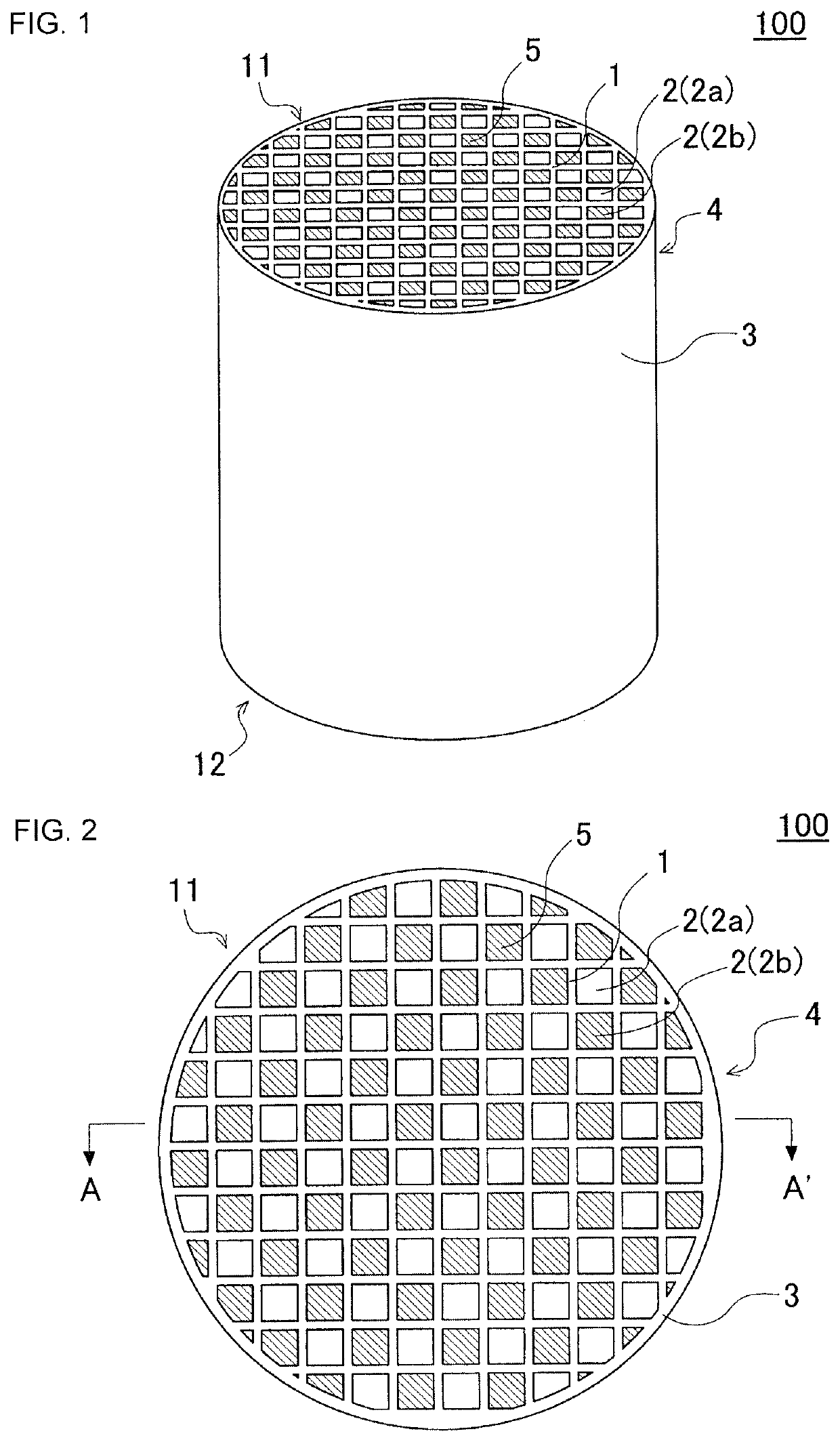
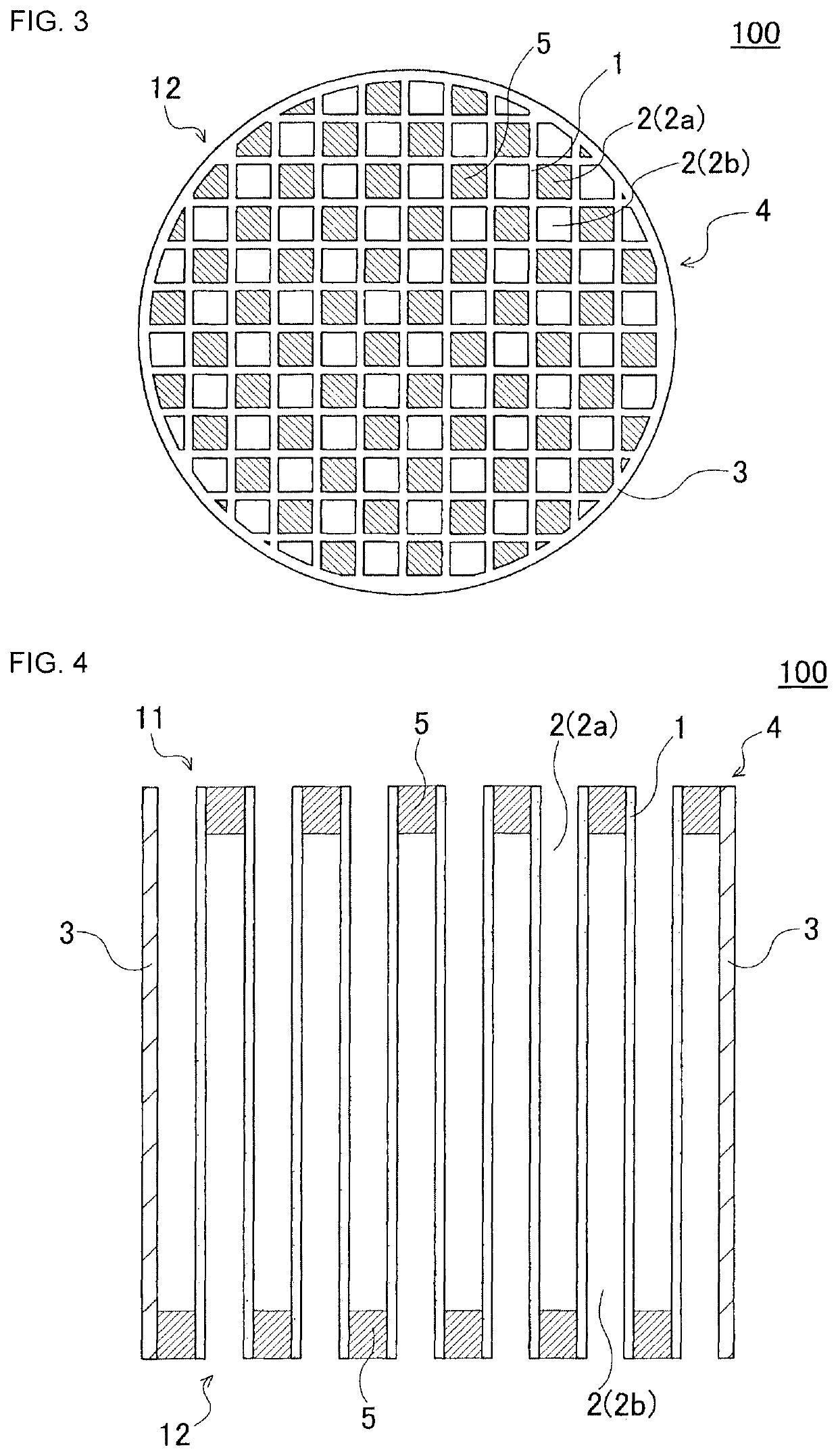
[0060]Next, the kneaded material was extruded by using a die for preparing a honeycomb formed body, a honeycomb formed body having a round pillar shape as a whole was obtained. The shape of the cell in the honeycomb formed body was a quadrangular shape.

[0061]The honeycomb formed body was then dried in a microwave dryer and further completely dried in a hot-air drier. Both end faces of the honeycomb formed bod...

examples 2 to 10

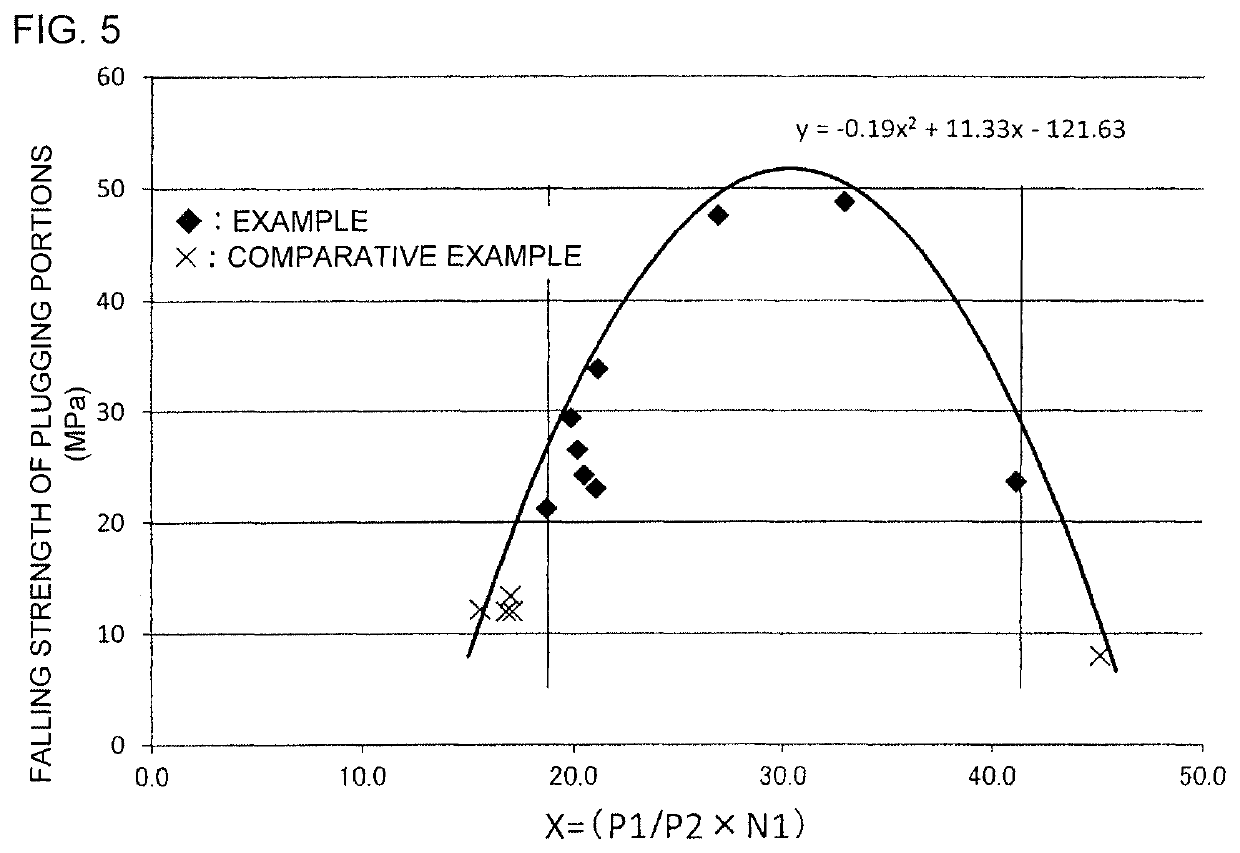
[0075]The porosity P1 of partition walls, the porosity P2 of plugging portions, and the occupancy N1 of partition walls were changed as shown in Table 1 to prepare honeycomb filters of Examples 2 to 10. The porosity P1 of partition walls was adjusted by changing the amount of the foamable resin as the pore former added to a cordierite forming raw material for preparing a kneaded material. The porosity P2 of plugging portions was also adjusted by changing the amount of the foamable resin as the pore former. The occupancy N1 of partition walls was adjusted by changing the slit width for forming partition walls in a die used for extrusion.


PUM

PropertyMeasurementUnit
thicknessaaaaaaaaaa
lengthaaaaaaaaaa
lengthaaaaaaaaaa

Abstract

A honeycomb filter including:a pillar-shaped honeycomb structure including porous partition walls; andporous plugging portions disposed on either one of end portions of each of the cells, whereina porosity (%) of the partition walls is defined as P1,a porosity (%) of the plugging portions is defined as P2,an occupancy (%) of the partition walls relative to an area of a cross section orthogonal to an extending direction of the cells of the honeycomb structure is defined as N1,the P1 is 50 to 65%,the P2 is 60 to 70%,the N1 is 22 to 39%, andX represented by Formula (1) satisfies a relation of Formula (2):X=P1 / P2×N1,  Formula (1):18.80≤−0.19X2+11.33X−121.63≤50.50.  Formula (2):

Description

[0001]The present application is an application based on JP-2018-066746 filed on Mar. 30, 2018 with Japan Patent Office, the entire contents of which are incorporated herein by reference.BACKGROUND OF THE INVENTIONField of the Invention[0002]The present invention relates to a honeycomb filter. More specifically, the present invention relates to a honeycomb filter capable of effectively preventing plugging portions provided to plug open ends of cells from falling or breaking.Description of the Related Art[0003]As a filter for trapping particulate matters in exhaust gas emitted from an internal combustion engine such as a diesel engine or as an apparatus for purifying poisonous gaseous components such as CO, HC, and NOx, a honeycomb filter having a honeycomb structure has been used (see Patent Document 1). The honeycomb structure has partition walls formed from a porous ceramic such as cordierite and silicon carbide, and the partition walls define a plurality of cells. The honeycomb f...

Claims


Application Information

Patent Timeline
Patent Type & Authority Patents(United States)
IPC IPC(8): B01D46/24F01N3/022
CPCB01D46/2455B01D46/244B01D46/2429B01D46/2459B01D46/2474F01N3/0222B01D2046/2433B01D2046/2481B01D2046/2496B01D2279/30B01D46/0002B01D46/2418B01D46/2482B01D46/24491B01D46/2476F01N2330/30F01N2330/06Y02T10/12B01D46/2498
Inventor KONNO, YOSHIKI
Owner NGK INSULATORS LTD
Why Eureka
Try Eureka