
Display device and multiplexer thereof

a technology of display device and multiplexer, which is applied in the direction of static indicating device, instruments, etc., can solve the problems of insufficient charging current of pixels in high-resolution displays, deleterious effects on touch sensing function precision, and display device acting erroneously

Active Publication Date: 2021-03-09
AU OPTRONICS CORP
View PDF21 Cites 0 Cited by
  • Summary
  • Abstract
  • Description
  • Claims
  • Application Information

AI Technical Summary

Benefits of technology

The present invention is about a display device and a multiplexer that can reduce impulse noises. This technology can make the display more stable and reliable.

Problems solved by technology

However, numerous of parasitic elements exist in the display device, and thus switching signals for controlling the multiplexers induce impulse noises in other signals during rising edges and falling edges of the switching signals.
As a result, the display device acts erroneously.
For example, if the display device is an integrated display device which has display function and touch sensing function, the impulse noises induced by the switching signals causes deleterious effects on precision of the touch sensing function.
Accordingly, if the foregoing solution is applied to a high-resolution display, pixels in the high-resolution display will encounter problems of insufficient charging currents.

Method used


Image

  • Display device and multiplexer thereof
  • Display device and multiplexer thereof
  • Display device and multiplexer thereof

Examples


Embodiment Construction

[0014]Reference will now be made in detail to the present embodiments of the disclosure, examples of which are illustrated in the accompanying drawings. Wherever possible, the same reference numbers are used in the drawings and the description to refer to the same or like parts.

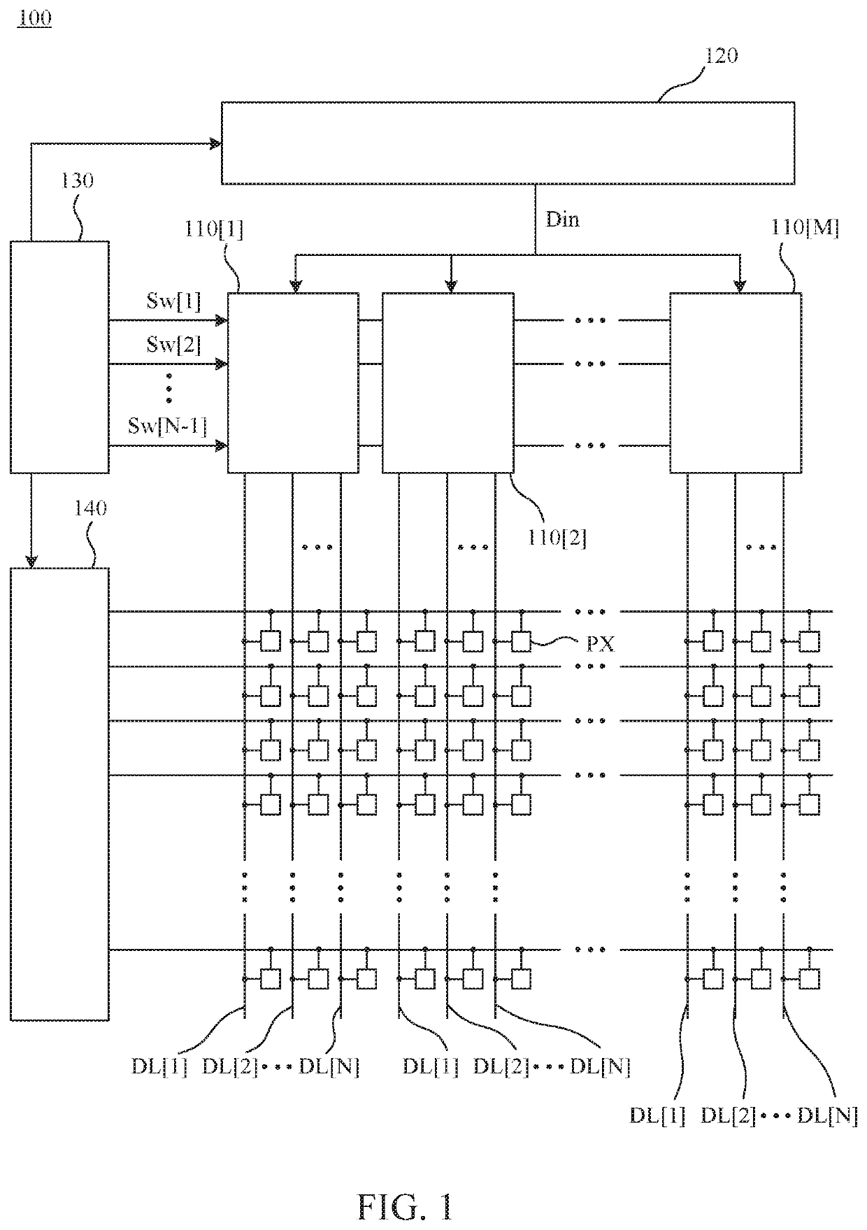
[0015]FIG. 1 is a simplified functional block diagram of a display device 100 according one embodiment of the present disclosure. The display device 100 comprises a plurality of multiplexers 110[1]-110[M], a source driver 120, a timing control circuit 130, a gate driver 140, and a plurality of pixels PX. Each of the multiplexers 110[1]-110[M] is configured to receive a data signal Din from the source driver 120, and configured to receive a plurality of switching signals Sw[1]-Sw[N−1] from the timing control circuit 130. Each of the multiplexers 110[1]-110[M] is further configured to output the data signal Din to the data lines DL[1]-DL[N] according to the switching signals Sw[1]-Sw[N−1]. The data lines DL[1]-...


PUM


Abstract

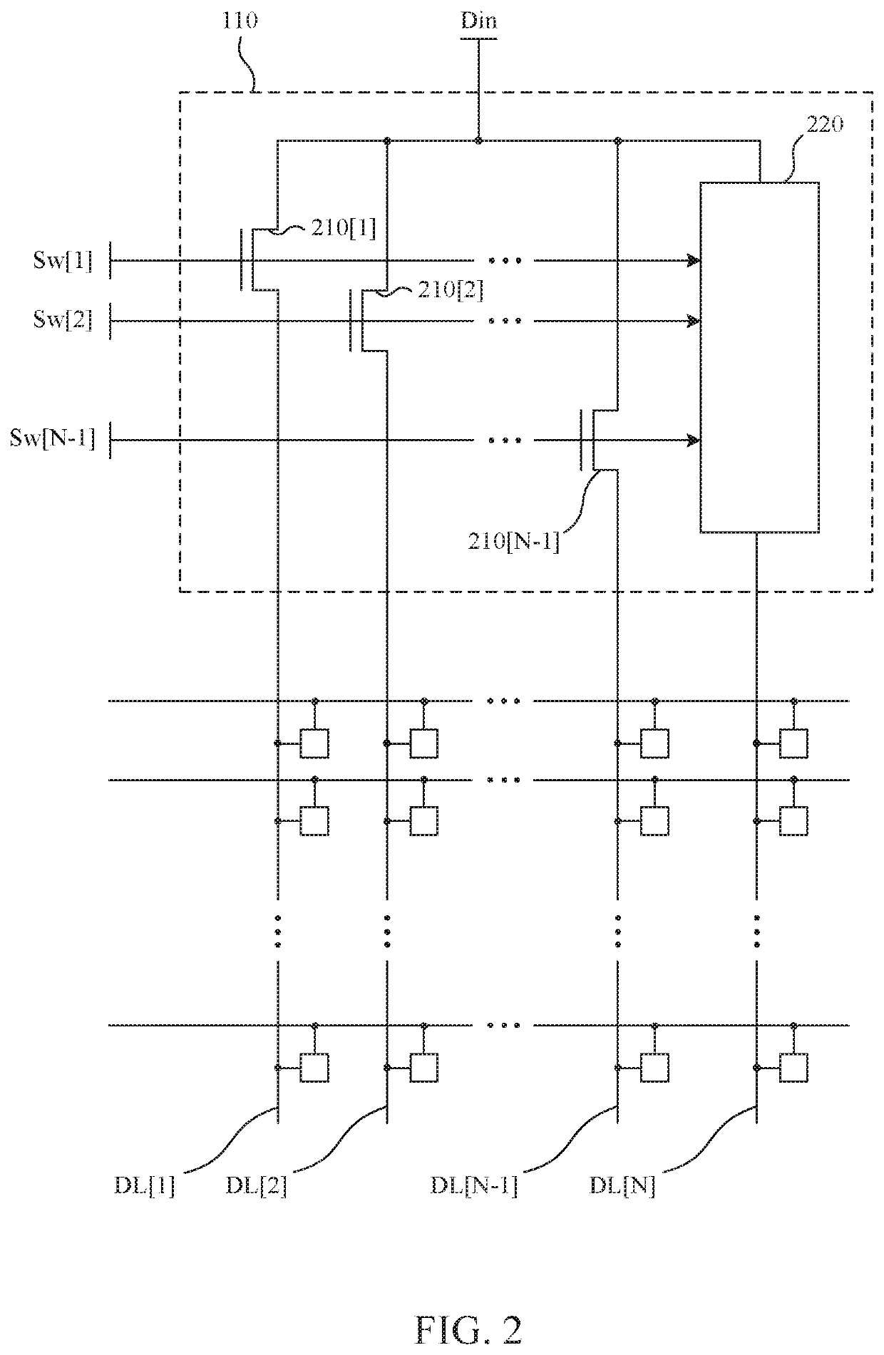
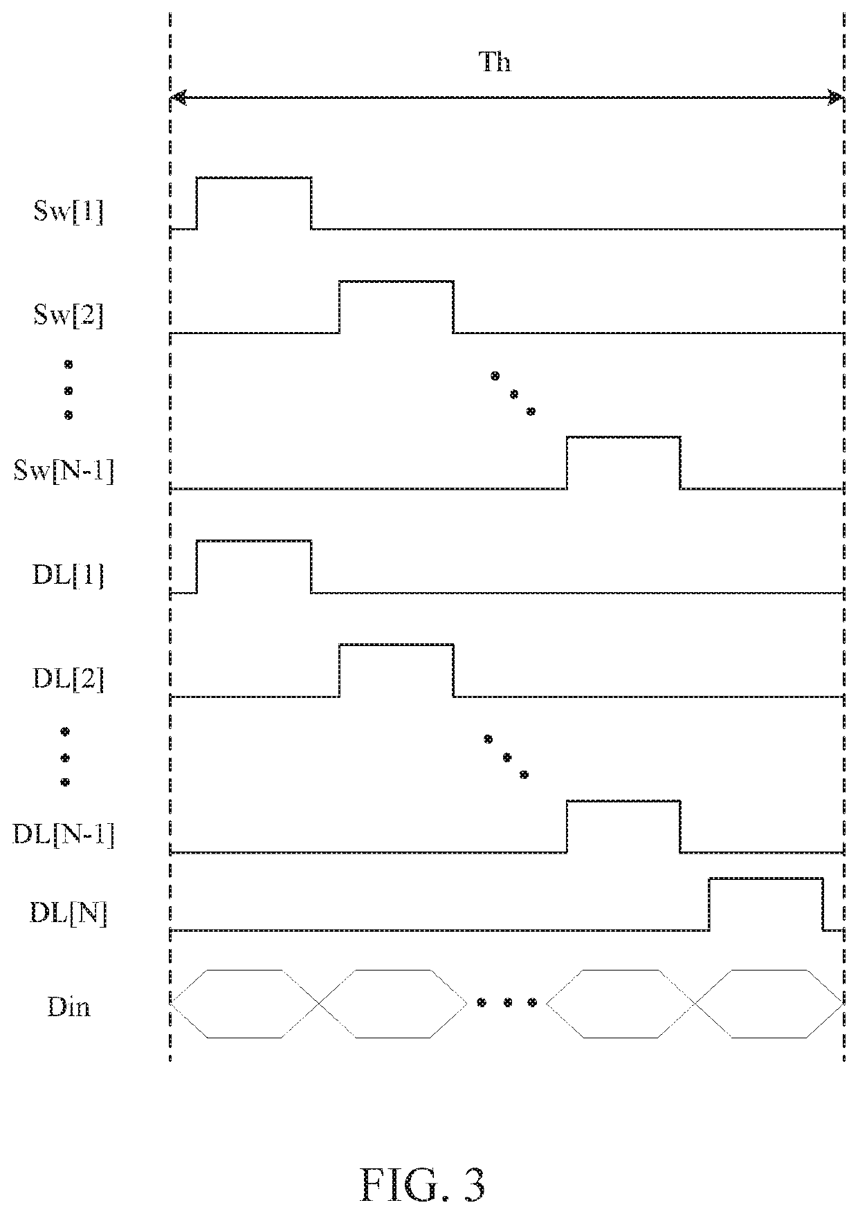
A display device comprises a plurality of pixels and a plurality of multiplexers. Each of the plurality of multiplexers is coupled with N data lines, and configured to receive N−1 switching signals and a data signal. N is a positive integer larger than or equal to 3, and each of the N data lines is coupled with one column of pixels of the plurality of pixels. When any of the N−1 switching signals has an enabling voltage level, the multiplexer is disabled from transmitting the data signal to an N-th data line of the N data lines. When each of the N−1 switching signals has a disabling voltage level, the multiplexer transmits the data signal to the N-th data line.

Description

CROSS-REFERENCE TO RELATED APPLICATION[0001]This application claims priority to Taiwan Application Serial Number 108101694, filed Jan. 16, 2019, which is herein incorporated by reference in its entirety.BACKGROUNDField of Invention[0002]The present disclosure relates to a display device and a multiplexer. More particularly, the present disclosure relates to the display device and the multiplexer capable of reducing impulse noises.Description of Related Art[0003]Common display devices use multiplexers to write data signals into columns of pixels, so as to reduce a number of pins required by driver IC. However, numerous of parasitic elements exist in the display device, and thus switching signals for controlling the multiplexers induce impulse noises in other signals during rising edges and falling edges of the switching signals. As a result, the display device acts erroneously. For example, if the display device is an integrated display device which has display function and touch sen...

Claims


Application Information

Patent Timeline
Patent Type & Authority Patents(United States)
IPC IPC(8): G09G3/20G09G3/36
CPCG09G3/2092G09G3/3677G09G3/3685G09G3/3688G09G2300/08G09G2300/0871G09G2310/0297G09G2330/021G09G3/20G09G2310/0275
Inventor CHEN, PING-LIN
Owner AU OPTRONICS CORP
Learn More