Bidirectional coupler

a bi-directional coupler and coupler technology, applied in the direction of coupling device connections, electrical apparatus, connections, etc., can solve the problems of increasing return loss, and achieve the effect of suppressing the increase in return loss

Active Publication Date: 2021-03-30
MURATA MFG CO LTD
View PDF12 Cites 3 Cited by
  • Summary
  • Abstract
  • Description
  • Claims
  • Application Information

AI Technical Summary

Benefits of technology

[0010]According to some embodiments of the present disclosure, it is possible to provide a bidirectional coupler capable of bidirectional detection with a suppressed increase in return loss at an output terminal for a detection signal.

Problems solved by technology

Accordingly, the adjustment of the impedance of the termination circuit can cause an impedance mismatch at the output terminal from which the detection signal is outputted, and can increase return loss.

Method used


Image

  • Bidirectional coupler
  • Bidirectional coupler
  • Bidirectional coupler

Examples


Embodiment Construction

[0022]The following describes an embodiment of the present disclosure with reference to the drawings. The same elements are assigned the same numerals and will not be repeatedly described.

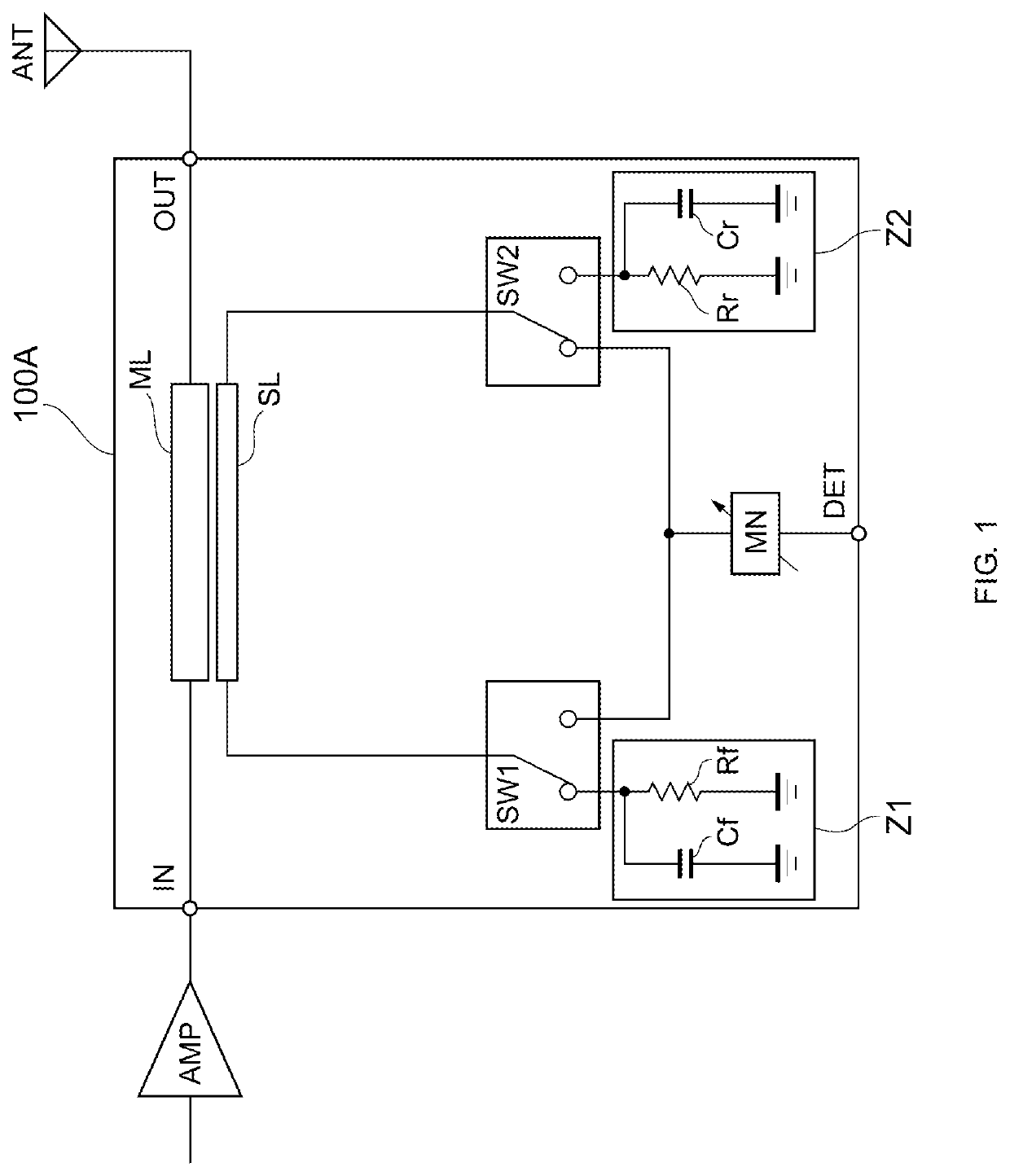
[0023]FIG. 1 is a diagram illustrating the configuration of a bidirectional coupler 100A according to an embodiment of the present disclosure. The bidirectional coupler 100A is capable of, for example, detecting a transmission signal that is transmitted from an amplifier circuit AMP to an antenna ANT (forward). The bidirectional coupler 100A is also capable of detecting a reflected signal from the antenna ANT to the amplifier circuit AMP (reverse).

[0024]As illustrated in FIG. 1, the bidirectional coupler 100A includes an input port IN, an output port OUT, a detection port DET, a main line ML, a sub-line SL, switches SW1 and SW2, termination circuits Z1 and Z2, and a matching network MN.

[0025]The main line ML (first main line) has one end connected to the input port IN (first port) and another end c...


PUM


Abstract

Bidirectional detection is performed with a suppressed increase in return loss at an output terminal. A bidirectional coupler includes a detection port, a main line connected to a first port and a second port, a sub-line, a termination circuit, a switch circuit that switches each of one end and another end of the sub-line to the termination circuit or the detection port, and a matching network disposed between the switch circuit and the detection port and including at least one of a first variable capacitor, a first variable inductor, or a first variable resistor. In a first mode for detecting a first signal, the switch circuit connects the one end of the sub-line to the detection port, and connects the other end of the sub-line to the termination circuit.

Description

[0001]This is a continuation of International Application No. PCT / JP2018 / 010963 filed on Mar. 20, 2018 which claims priority from Japanese Patent Application No. 2017-059815 filed on Mar. 24, 2017. The contents of these applications are incorporated herein by reference in their entireties.BACKGROUND OF THE DISCLOSUREField of the Disclosure[0002]The present disclosure relates to a bidirectional coupler.Description of the Related Art[0003]In wireless communication devices such as mobile phones, detection circuits are used to detect signal levels. For example, Patent Document 1 discloses a bidirectional coupler including a direction-switching switch and capable of detecting signal levels of both a transmission signal outputted to an antenna and a reflected signal from the antenna. In this configuration, adjusting the impedance of a termination circuit in accordance with the direction, frequency band, and so on of the signal to be detected can improve the directivity of the bidirectiona...

Claims


Application Information

Patent Timeline
Patent Type & Authority Patents(United States)
IPC IPC(8): H01P5/04H01R13/66
CPCH01P5/04H01R13/6616H01R13/6625H01R13/6633H01P5/185
Inventor KIM, RYANGSUSHIMIZU, KATSUYASHIGENO, YASUSHITOKUDA, DAISUKEFUKASAWA, MIKIKO
Owner MURATA MFG CO LTD
Why Eureka
Try Eureka