Signal transceiver and adaptability impedance switching circuit

A signal transceiver and impedance switching technology, applied in electrical components, transmission systems, etc., can solve problems such as system performance deterioration

Active Publication Date: 2014-02-12
WISTRON NEWEB
View PDF4 Cites 0 Cited by
  • Summary
  • Abstract
  • Description
  • Claims
  • Application Information

AI Technical Summary

Problems solved by technology

From the above, it can be seen that if the signal transceiver 10 is operated in a power-off state, the system performance will indeed deteriorate.

Method used


Image

  • Signal transceiver and adaptability impedance switching circuit
  • Signal transceiver and adaptability impedance switching circuit
  • Signal transceiver and adaptability impedance switching circuit

Examples


Embodiment Construction

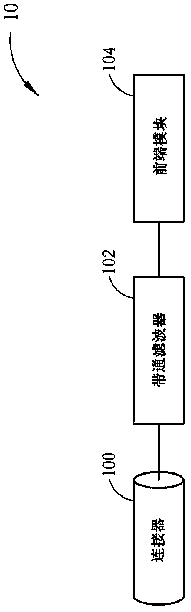
[0037] Please refer to image 3 , image 3 It is a schematic diagram of a signal transceiver 30 according to an embodiment of the present invention. The signal transceiver 30 includes a connector 300 , a bandpass filter 302 , an adaptive impedance switching circuit 304 and a front-end module 306 . The connector 300 , the bandpass filter 302 , and the front-end module 306 are respectively the same as the connector 100 , the bandpass filter 102 , and the front-end module 104 of the conventional signal transceiver 10 , and will not be repeated here. The adaptive impedance switching circuit 304 is coupled to the bandpass filter 302 and the front-end module 306 for switching the impedance between the bandpass filter 302 and the front-end module 306 .

[0038] For the implementation of the adaptive impedance switching circuit 304, please refer to Figure 4A . The adaptive impedance switching circuit 304 includes an input terminal 400 , an output terminal 402 , a voltage input ci...


PUM


Abstract

The invention discloses a signal transceiver which comprises a connecting device used for receiving a signal, a band-pass filter connected with the connecting device in a coupled mode and used for filtering the signal, a front-end module used for demodulating the signal and an adaptability impedance switching circuit which is connected between the front-end module and the band-pass filter in a coupled mode and used for switching a resistance value between the band-pass filter and the front-end module.

Description

technical field [0001] The present invention refers to a signal transceiver and an adaptive impedance switching circuit, in particular to a signal transceiver and an adaptive impedance switching circuit that can effectively improve return loss in a power-off state. Background technique [0002] Ethernet over Coax (EoC) is a transmission technology of Ethernet signals on coaxial cables. Its purpose is to use the existing cable TV infrastructure to connect to the Internet or broadband data transmission. , Compatible with existing cable TV (or satellite TV) broadcasting signals, achieving the purpose of transmitting data signals on the same coaxial cable at the same time. Among them, the multimedia network standard formulated by the Multimedia over Coax Alliance (MoCA) has high-speed and high-quality-of-service (QoS) functions required for glitch-free streaming media, etc., through the existing The coaxial cable sends the signal to each user end, and the user end only needs a ...

Claims


Application Information

Patent Timeline
IPC IPC(8): H04B1/40H04B1/44
Inventor 吕正雄黄宜勤邢琼雯
Owner WISTRON NEWEB
Why Eureka
Try Eureka