Check patentability & draft patents in minutes with Patsnap Eureka AI!

System for coherent imaging in dynamic engagements

a dynamic engagement and coherent imaging technology, applied in the field of coherent imaging, can solve problems such as the imposition of interference features on the coherent signal

Active Publication Date: 2021-05-04
RAYTHEON CO
View PDF21 Cites 0 Cited by
  • Summary
  • Abstract
  • Description
  • Claims
  • Application Information

AI Technical Summary

Benefits of technology

Enables coherent imaging in dynamic environments with reduced detector bandwidth requirements, maintaining image quality and allowing for real-time compensation of longitudinal velocity changes, thus extending the system's utility in highly dynamic engagements.

Problems solved by technology

However, object motion on the order of the wavelength of light imparts interference features to the coherent signal.

Method used


Image

  • System for coherent imaging in dynamic engagements
  • System for coherent imaging in dynamic engagements
  • System for coherent imaging in dynamic engagements

Examples


Embodiment Construction

[0012]It should be understood at the outset that, although exemplary embodiments are illustrated in the figures and described below, the principles of the present disclosure may be implemented using any number of techniques, whether currently known or not. The present disclosure should in no way be limited to the exemplary implementations and techniques illustrated in the drawings and described below. Additionally, unless otherwise specifically noted, articles depicted in the drawings are not necessarily drawn to scale.

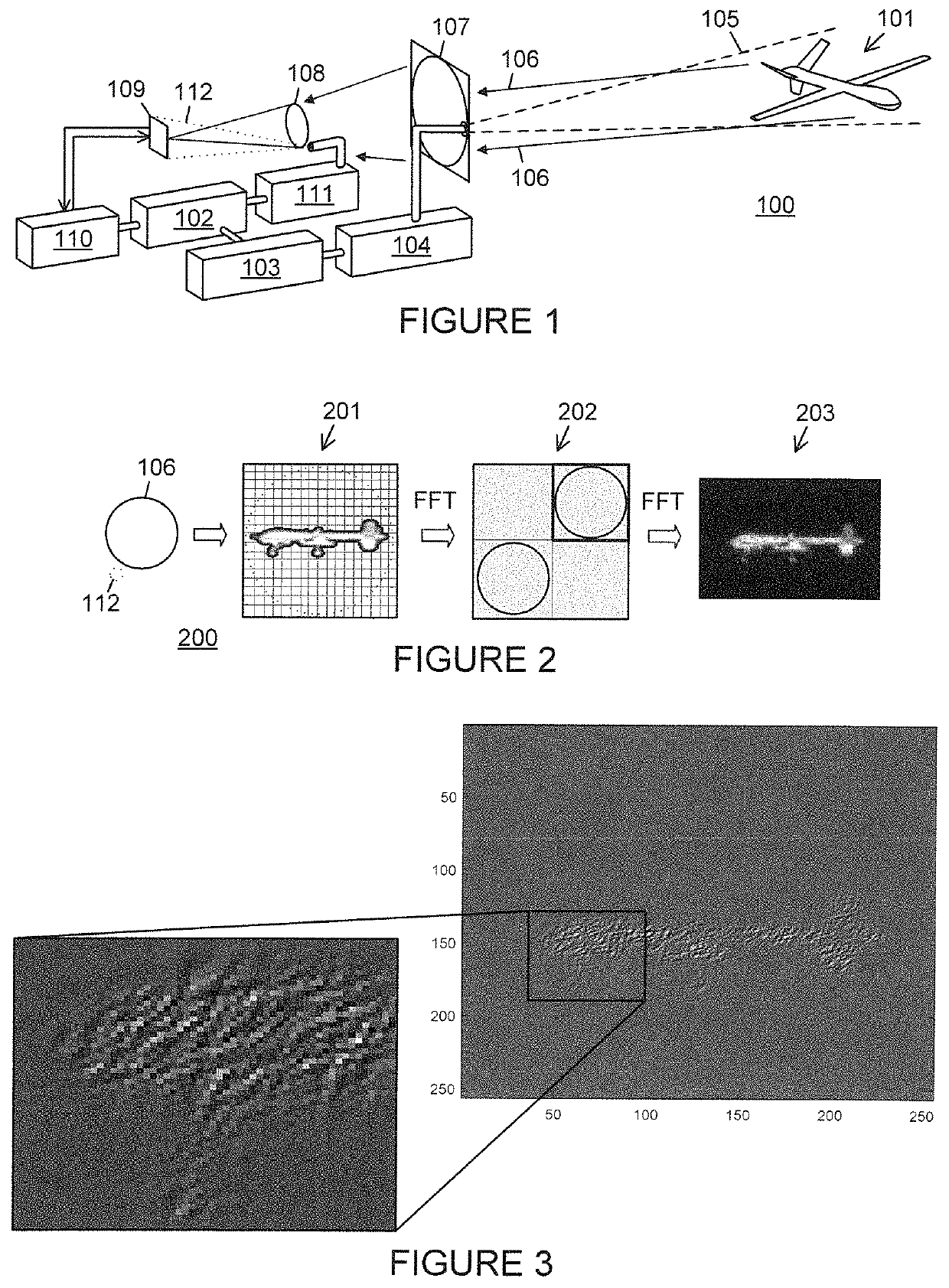
[0013]Coherent imaging systems, where an active laser-based system is employed to measure the amplitude and phase of an image, rely on the interference between a local oscillator (LO) beam and the return from a coherently illuminated target. Coherent imaging provides great value for interrogating distant objects. Specific elements of this value include: improved performance with low light levels, three-dimensional (3D) imaging, correction of optical aberrations, and e...


PUM


Abstract

A coherent imaging system produces coherent flood illumination directed toward a remote object and local oscillator (LO) illumination derived based on a same master oscillator as the flood illumination. A Doppler sensor receives the LO illumination and a return of flood illumination reflected off the object. Doppler shift data from the Doppler sensor, corresponding to a longitudinal velocity of the object relative to the imaging system, is used to produce Doppler-shifted LO illumination received by a low bandwidth, large format focal plane array (FPA), together with the return illumination from the object. Interference between the Doppler-shifted LO illumination and the return illumination facilitates producing an image of the object with the low bandwidth FPA despite the longitudinal velocity. Pixel intensities from the FPA are integrated over a period approaching the maximum interference frequency. The Doppler sensor and FPA may concurrently process return for a high energy laser target spot.

Description

TECHNICAL FIELD[0001]The present disclosure is directed in general to coherent imaging, and, more particularly, to coherent imaging in the context of relative movement between an imaged object and the sensor(s).BACKGROUND OF THE DISCLOSURE[0002]Coherent imaging methods have value for obtaining image-based information from distant objects. However, object motion on the order of the wavelength of light imparts interference features to the coherent signal.SUMMARY OF THE DISCLOSURE[0003]A coherent imaging system employs a flood illumination source to produce coherent flood illumination derived based on an output of a master oscillator (MO) and directed toward a remote object. A local oscillator (LO) illumination source produces LO illumination derived from an LO based on the MO. A Doppler sensor configured receives the LO illumination and at least part of return illumination of the coherent flood illumination reflected off the remote object. One or more processors employ the output of t...

Claims


Application Information

Patent Timeline
Patent Type & Authority Patents(United States)
IPC IPC(8): G01S17/89G01S17/58G01S7/481F41H13/00
CPCG01S17/89G01S7/4812G01S17/58F41H13/005
Inventor MARRON, JOSEPHHALMOS, MAURICE J.GRAYER, JUSTIN S.SITTER, JR., DAVID N.ERTEN, GAMZE
Owner RAYTHEON CO
Features
  • R&D
  • Intellectual Property
  • Life Sciences
  • Materials
  • Tech Scout
  • Unparalleled Data Quality
  • Higher Quality Content
  • 60% Fewer Hallucinations
Learn More