Downhole device and downhole system

a technology of a downhole and a ball seat, which is applied in the direction of fluid removal, borehole/well accessories, construction, etc., can solve the problems of difficult retrieval process and failure of round ball rolling in the ball seat, and achieve the effect of faster and more reliable way

Active Publication Date: 2021-05-11
WELLTEC AS
View PDF11 Cites 1 Cited by
  • Summary
  • Abstract
  • Description
  • Claims
  • Application Information

AI Technical Summary

Benefits of technology

[0006]It is an object of the present invention to wholly or partly overcome the above disadvantages and drawbacks of the prior art. More specifically, it is an object to provide an improved way of stimulating several production zones in a faster and more reliable way than with prior art solutions.
[0007]The above objects, together with numerous other objects, advantages and features, which will become evident from the below description, are accomplished by a solution in accordance with the present invention by a downhole device for being moved downwards in a well by fluid to assist stimulation of a production zone of the well, the well comprising a well tubular structure having a first opening and a first movable sleeve arranged opposite the first opening, the well tubular structure having an inner diameter, the downhole device having an axial extension and comprising:

Problems solved by technology

Using this ball dropping process is inexpensive, but also very time-consuming since the balls have to be retrieved one by one.
Furthermore, retrieving a round ball rolling in a ball seat can be very difficult, and the retrieval process may therefore fail.

Method used


Image

  • Downhole device and downhole system
  • Downhole device and downhole system
  • Downhole device and downhole system

Examples


Embodiment Construction

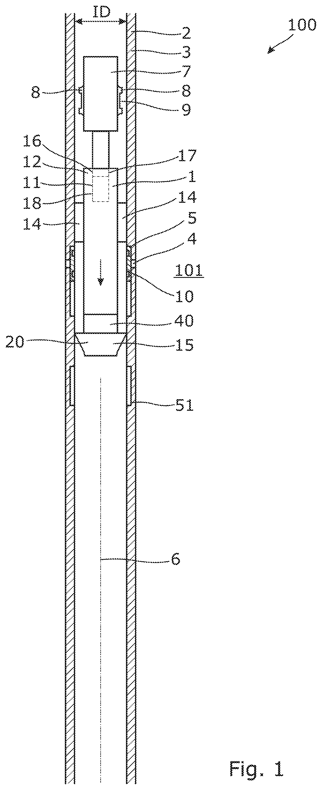
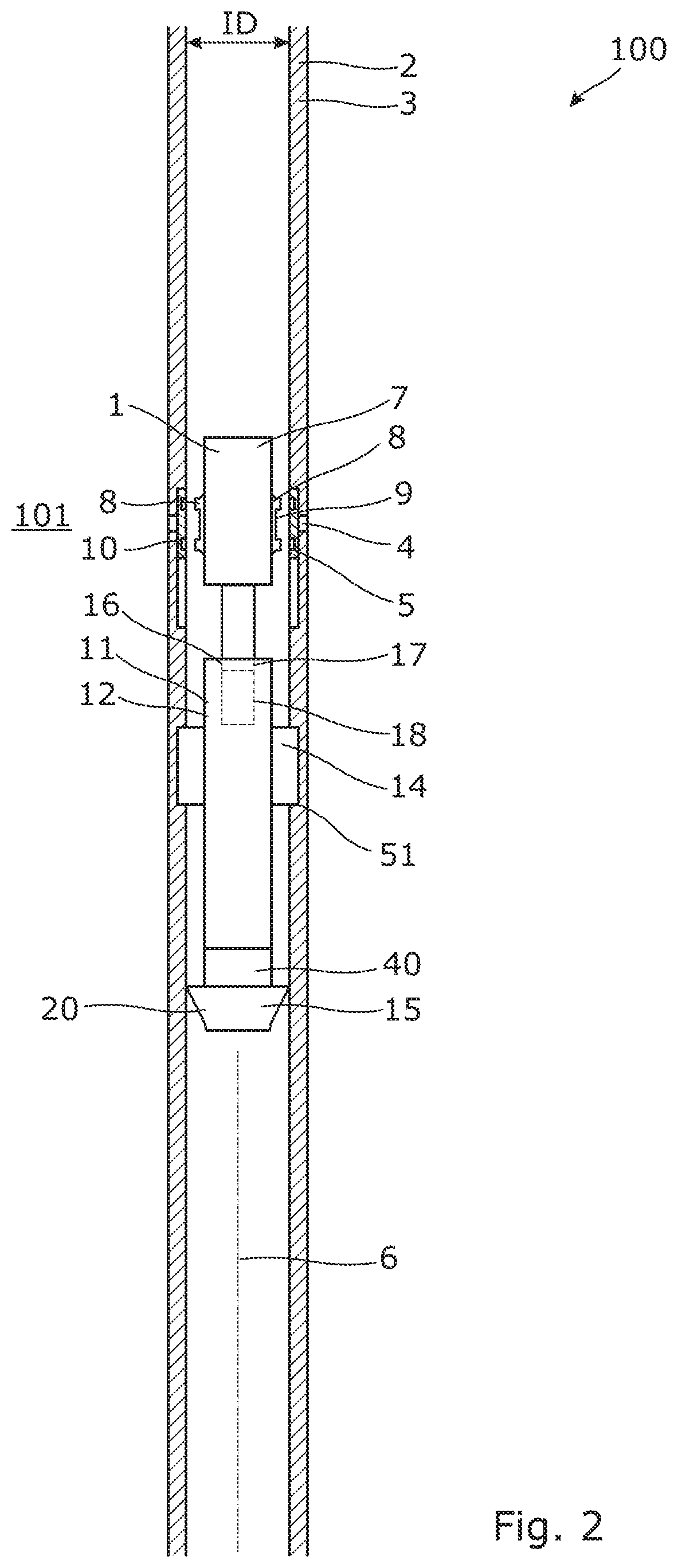
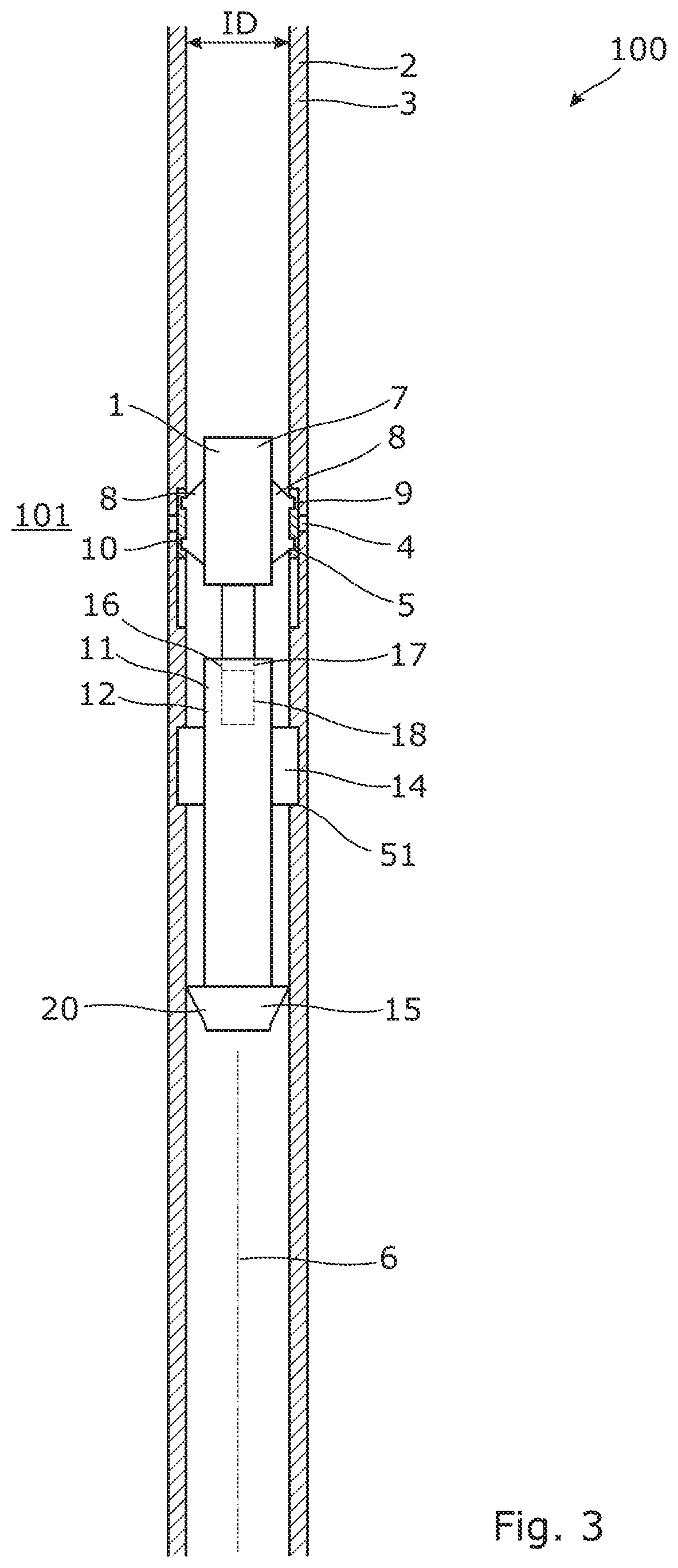
[0093]FIG. 1 shows a downhole device 1 moving downwards in a well 2 by means of fluid flowing down the well, thereby pressing the downhole device 1 down a well tubular structure 3 in the well. The downhole device 1 is used for assisting stimulation of a production zone 101 of the well by ejecting fluid out through a first opening 4 of the well tubular structure 3 having a first sleeve 5 arranged opposite the first opening. The sleeve 5 is opened to eject stimulation fluid out of the opening and closed again to pressurise the well tubular structure again when ejecting fluid out through another opening.

[0094]The downhole device 1 comprises a first part 7 comprising two projection elements 8 having a profile 9 matching grooves 10 in the sleeve 5, and a second part 11 comprising a body 12, two anchor elements 14 projectable from the body for anchoring the second part in the well tubular structure, and a sealing element 15 configured to seal against the well tubular structure 3 in order ...


PUM


Abstract

The present invention relates to a downhole device for being moved downwards in a well by fluid to assist stimulation of a production zone of the well, the well comprising a well tubular structure having a first opening and a first movable sleeve arranged opposite the first opening, and the well tubular structure having an inner diameter, the downhole device having an axial extension, and comprising: a first part comprising two projection elements having a profile matching grooves in the sleeve, and a second part comprising: a body, two anchor elements projectable from the body for anchoring the second part in the well tubular structure, and a sealing element configured to seal against the well tubular structure, the downhole device further comprising: a displacement mechanism comprising a piston movable within a piston cylinder to displace, in the axial extension, the first part in relation to the second part when anchored in the well tubular structure to operate the sleeve. The invention also relates to a downhole system for stimulating a formation surrounding a well tubular structure of a well. Finally, the present invention relates to a stimulation method for stimulating a formation by means of a downhole system according to the invention.

Description

[0001]This application claims priority to EP Patent Application No. 16155044.7 filed Feb. 10, 2016, the entire content of which is hereby incorporated by reference.FIELD OF THE INVENTION[0002]The present invention relates to a downhole device for being moved downwards in a well by fluid to assist stimulation of a production zone of the well. The invention also relates to a downhole system for stimulating a formation surrounding a well tubular structure of a well. Finally, the present invention relates to a stimulation method for stimulating a formation by means of a downhole system according to the invention.BACKGROUND ART[0003]When stimulating production zones in wells, a first ball is dropped into the well and flows with the well fluid until it reaches a ball seat which it is not able to pass, causing the ball to seat in the ball seat of a first sleeve. A continuous pumping of fluid into the well results in a pressure on the ball moving the sleeve from a closed position to an open...

Claims


Application Information

Patent Timeline
Patent Type & Authority Patents(United States)
IPC IPC(8): E21B43/26E21B23/02E21B23/01E21B33/1295E21B34/14
CPCE21B43/26E21B23/01E21B23/02E21B33/1295E21B34/14E21B2200/06E21B23/042
Inventor KUMAR, SATISH
Owner WELLTEC AS
Why Eureka
Try Eureka