
Vital signs information synchronization system, vital signs information synchronization method, and vital signs information detecting sensor

a vital signs and information synchronization technology, applied in the field of vital signs information synchronization system, vital signs information synchronization method, and vital signs information detecting sensor, can solve the problems of inability of the receiving side of vital signs information, electrocardiogram data and pulse data cannot be displayed in a state,

Active Publication Date: 2021-06-01
NIHON KOHDEN CORP
View PDF12 Cites 0 Cited by
  • Summary
  • Abstract
  • Description
  • Claims
  • Application Information

AI Technical Summary

Benefits of technology

The present disclosure is for a system that synchronizes information detected from two vital signs sensors attached to a living body. The first sensor detects over time first vital signs information such as electrocardiogram data and pulse data, and sends it to an information processing device. The second sensor detects over time second vital signs information and sends it to the device as well. The device then displays the two sets of information on the screen in a synchronized state based on the motion information detected by the sensors. The technical effect of this system is that it allows treatment of the two sets of vital signs information as if they are detected simultaneously, even if the sensors may not be synchronized in their transmissions.

Problems solved by technology

Therefore, even if sets of vital signs information are detected at the same time, it is impossible for the receiving side of the vital signs information to recognize the vital signs information which is detected by each of the vital signs information detecting sensors as the sets of vital signs information which are detected at the same time.
As a result, for example, electrocardiogram data and pulse data cannot be displayed in a state where the two kinds of data are synchronized.

Method used


Image

  • Vital signs information synchronization system, vital signs information synchronization method, and vital signs information detecting sensor
  • Vital signs information synchronization system, vital signs information synchronization method, and vital signs information detecting sensor
  • Vital signs information synchronization system, vital signs information synchronization method, and vital signs information detecting sensor

Examples


first embodiment

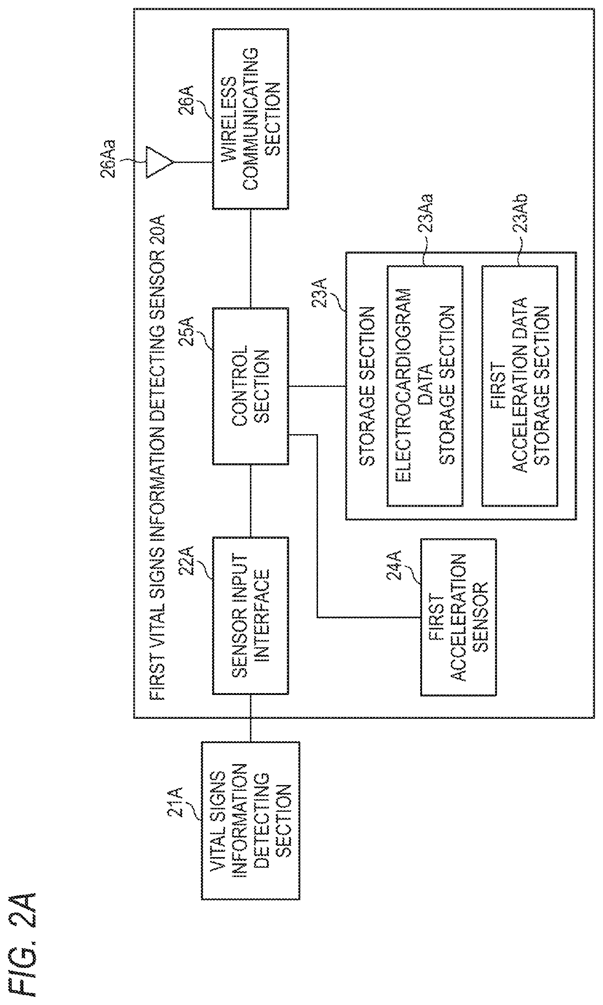
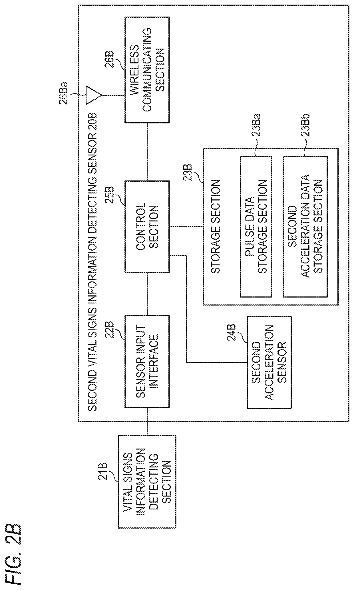
[0034]Hereinafter, a medical telemetry system 10 which is a first embodiment of the present disclosure will be described with reference to the accompanying drawings. In the drawings, components which correspond to each other are denoted by the same reference numerals or symbols. Duplicative description for such components will be omitted.

[0035]FIG. 1 is a schematic diagram of the medical telemetry system 10.

[0036]As illustrated in FIG. 1, a vital signs information synchronization system (hereinafter, referred to as the medical telemetry system 10) includes a first vital signs information detecting sensor 20A, a second vital signs information detecting sensor 20B, an information processing device (hereinafter, referred to as a receiver 30), etc. In the case where the first vital signs information detecting sensor 20A and the second vital signs information detecting sensor 20B are not particularly distinguished from each other, the sensors will be hereinafter referred to as the vital ...

second embodiment

[0092]Next, a medical telemetry system 10A according to a second embodiment of the present disclosure will be described with reference to the accompanying drawings. In the drawings, components which correspond to each other are denoted by the same reference numerals or symbols. Duplicative description for such components will be omitted.

[0093]As illustrated in FIG. 1, a vital signs information synchronization system (hereinafter, referred to as the medical telemetry system 10A) includes a first vital signs information detecting sensor 20C, a second vital signs information detecting sensor 20D, an information processing device (hereinafter, referred to as the receiver 30), etc. In the case where the first vital signs information detecting sensor 20C and the second vital signs information detecting sensor 20D are not particularly distinguished from each other, the sensors will be hereinafter referred to as the vital signs information detecting sensor 20.

[0094]FIG. 8A is a schematic ha...

third embodiment

[0133]Next, a medical telemetry system 10B according to a third embodiment of the present disclosure will be described with reference to the accompanying drawings. In the drawings, components which correspond to each other are denoted by the same reference numerals or symbols. Duplicative description for such components will be omitted.

[0134]As illustrated in FIG. 1, a vital signs information synchronization system (hereinafter, referred to as the medical telemetry system 10B) includes a first vital signs information detecting sensor 20E, a second vital signs information detecting sensor 20F, an information processing device (hereinafter, referred to as the receiver 30), etc. In the case where the first vital signs information detecting sensor 20E and the second vital signs information detecting sensor 20F are not particularly distinguished from each other, the sensors will be hereinafter referred to as the vital signs information detecting sensor 20.

[0135]FIG. 13A is a schematic ha...


PUM


Abstract

A first vital signs information detecting sensor and a second vital signs information sensor are attached to a living body. The first vital signs information detecting sensor detects over time first vital signs information and first motion information of the living body. The first vital signs information and the first motion information are transmitted from the first vital signs information detecting sensor to a receiver. The second vital signs information detecting sensor detects over time second vital signs information and second motion information of the living body. The second vital signs information and the second motion information are transmitted from the second vital signs information detecting sensor to the receiver. The first vital signs information and the second vital signs information are displayed on a display of the receiver in a synchronized state, on the basis of the first motion information and the second motion information.

Description

CROSS-REFERENCE TO RELATED APPLICATION(S)[0001]This application is based upon and claims the benefit of priority from prior Japanese patent application No. 2017-143374, filed on Jul. 25, 2017, the entire contents of which are incorporated herein by reference.BACKGROUND1. Technical Field[0002]The present disclosure relates to a vital signs information synchronization system, a vital signs information synchronization method, and a vital signs information detecting sensor.2. Background Art[0003]A vital signs information detecting sensor equipped with a wireless communication section (a medical telemeter) is known in the field of medical devices. For example, Japanese Patent Publication No. 2014-068718A discloses such a sensor.[0004]In the case where a plurality of vital signs information detecting sensors such as an electrocardiogram detecting sensor and a pulse detecting sensor are used while attached to the same living body, however, the vital signs information detecting sensors wire...

Claims


Application Information

Patent Timeline
Patent Type & Authority Patents(United States)
IPC IPC(8): A61B5/00A61B5/0205A61B5/11A61B5/024A61B5/318A61B5/308
CPCA61B5/7289A61B5/0006A61B5/0205A61B5/11A61B5/02438A61B5/318A61B5/7425A61B2562/0219A61B5/33
Inventor KONNO, NORIHITONAGASAWA, YOSUKE
Owner NIHON KOHDEN CORP
Learn More