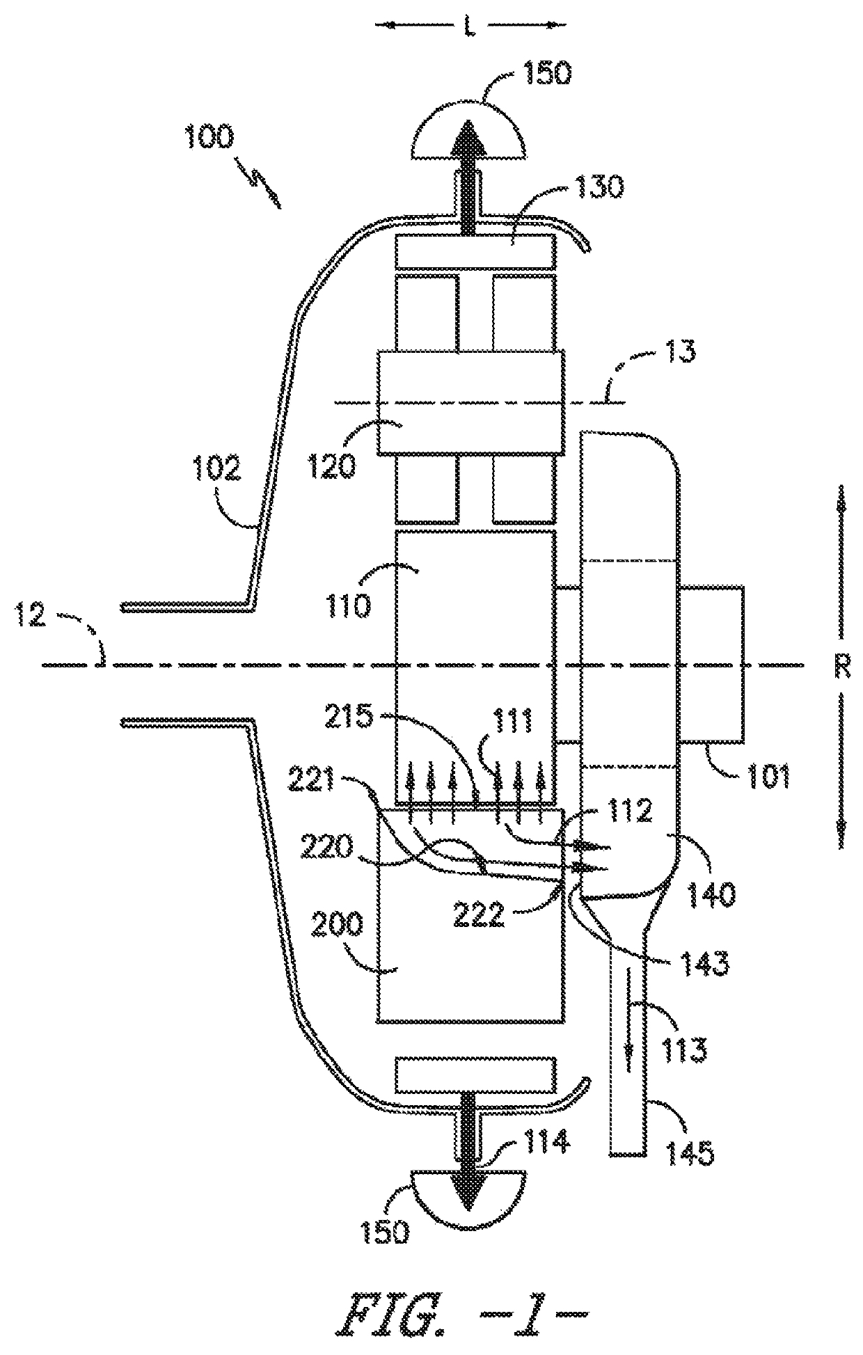
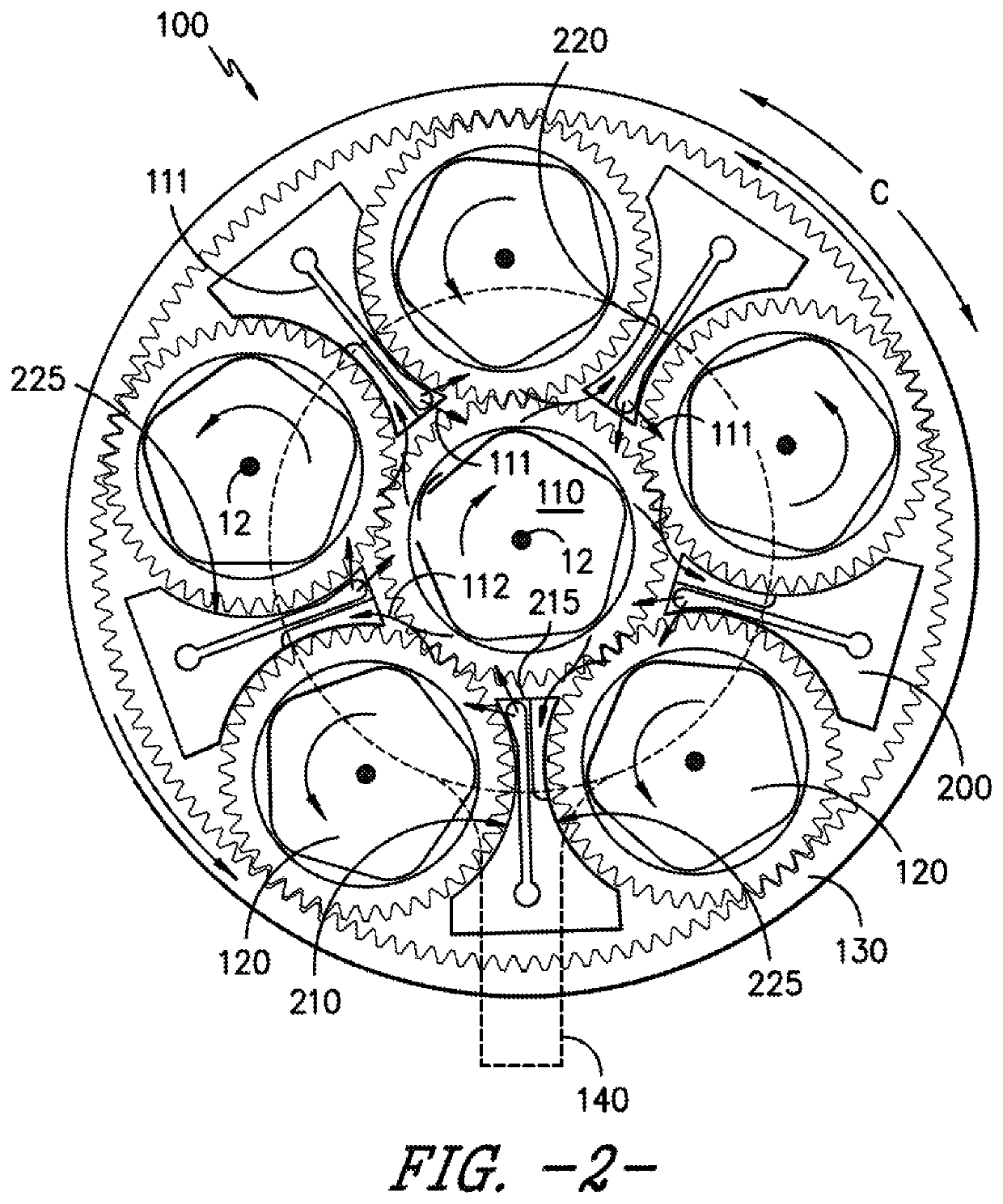
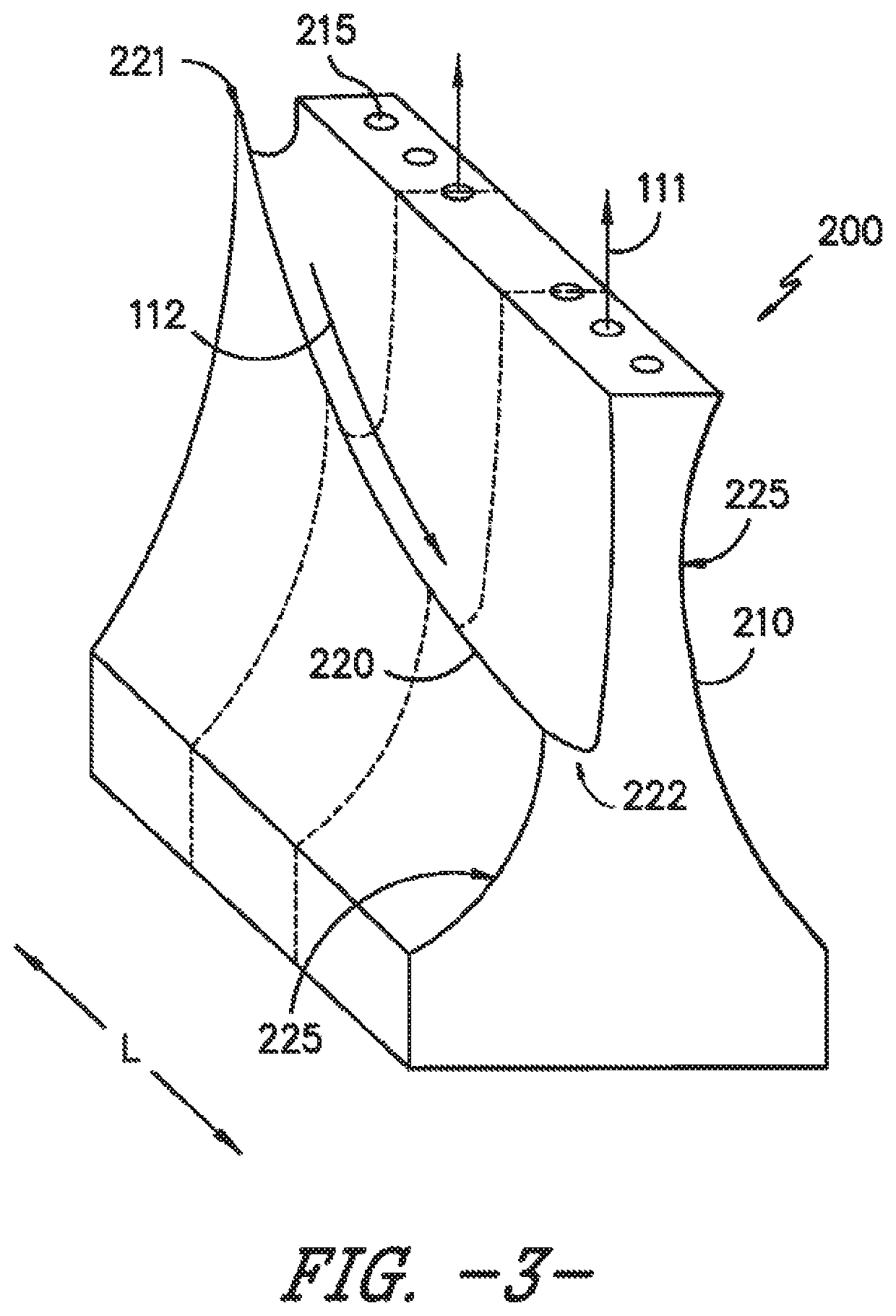
Scavenge system for gear assembly

a gear assembly and lubricant technology, applied in the direction of gear lubrication/cooling, motors, engine fuctions, etc., can solve the problems of reducing the quantity of lubricant required, the size of the lubricant system and/or the gear assembly, and the power loss of the gear assembly

Active Publication Date: 2021-06-01
GE AVIO
View PDF24 Cites 4 Cited by
  • Summary
  • Abstract
  • Description
  • Claims
  • Application Information

AI Technical Summary

Problems solved by technology

However, the lubricant injected into the gear meshes may result in gear assembly power losses when lubricant is insufficiently scavenged from the gear assembly.
Furthermore, lubricant systems and gear assemblies may create a limit as to the quantity of lubricant required and the size of the lubricant system and / or gear assembly.

Method used


Image

  • Scavenge system for gear assembly
  • Scavenge system for gear assembly
  • Scavenge system for gear assembly

Examples


Embodiment Construction

[0019]Reference now will be made in detail to embodiments of the invention, one or more examples of which are illustrated in the drawings. Each example is provided by way of explanation of the invention, not limitation of the invention. In fact, it will be apparent to those skilled in the art that various modifications and variations can be made in the present invention without departing from the scope or spirit of the invention. For instance, features illustrated or described as part of one embodiment can be used with another embodiment to yield a still further embodiment. Thus, it is intended that the present invention covers such modifications and variations as come within the scope of the appended claims and their equivalents.

[0020]As used herein, the terms “first”, “second”, and “third” may be used interchangeably to distinguish one component from another and are not intended to signify location or importance of the individual components.

[0021]The terms “upstream” and “downstre...


PUM


Abstract

A gear assembly including a first gear disposed at a centerline axis of the gear assembly; a second gear coupled to the first gear in adjacent radial arrangement; and a spraybar assembly disposed between a plurality of the second gear. The spraybar assembly defines an elongated neck extended between the plurality of second gear. A supply opening is defined through the elongated neck and the elongated neck defines a groove extended along a longitudinal direction.

Description

FIELD[0001]The present subject matter relates generally to gear assemblies.BACKGROUND[0002]Mechanical and electro-mechanical systems, such as turbine engines including industrial and aviation gas turbines and wind turbines, include gear assemblies to change an input or output rotational speed between two or more shafts such as to optimize turbine engine efficiency and performance. Lubricant systems for such gear assemblies are designed to supply and scavenge lubricant injected into gear meshes. However, the lubricant injected into the gear meshes may result in gear assembly power losses when lubricant is insufficiently scavenged from the gear assembly. Furthermore, lubricant systems and gear assemblies may create a limit as to the quantity of lubricant required and the size of the lubricant system and / or gear assembly.[0003]As such, there is a need for a gear assembly and lubricant system that improves lubricant scavenging and reduces gear assembly power losses, lubricant quantities...

Claims


Application Information

Patent Timeline
Patent Type & Authority Patents(United States)
IPC IPC(8): F16H57/04F02C7/36F01D25/18F03D80/70F03D15/00
CPCF16H57/046F16H57/0409F16H57/0423F16H57/0457F16H57/0479F16H57/0486F01D25/18F02C7/36F03D15/00F03D80/70F05B2260/40311F05B2260/98F05D2260/40311F05D2260/98
Inventor BARAGGIA AU YEUNG, SAYPENZAGATO, GIULIO
Owner GE AVIO
Why Eureka
Try Eureka