System and method for in-situ characterization and inspection of additive manufacturing deposits using transient infrared thermography

a technology of in-situ characterization and in-situ inspection of additive manufacturing deposits, applied in additive manufacturing, manufacturing data acquisition/processing, manufacturing tools, etc., can solve problems such as limited success, inability to build quality, and inability to determine and control

Active Publication Date: 2021-06-08
NASA
View PDF23 Cites 0 Cited by
  • Summary
  • Abstract
  • Description
  • Claims
  • Application Information

AI Technical Summary

Benefits of technology

[0005]The present invention described herein provides systems and methods for the real time inspection of additive manufacturing deposits using infrared thermography. Various embodiments may enable the measurement of material properties and the detection of defects during the additive manufacturing process. Various embodiments may enable the characterization of deposition quality, as well as the detection of deposition defects, such as voids, cracks, disbonds, etc., as a structure is manufactured layer by layer in an additive manufacturing process. Various embodiments may enable quantitative inspection images to be archived and associated with the manufactured structure to document the manufactured structure's structural integrity.
[0010]Various embodiments of the invention may include thermal nondestructive evaluation being performed using image processing techniques to calculate the temporal thermal response at a given spatial point and to use thermal models or processing techniques, such as principal component analysis, time derivative, etc. The thermal models may be used to calculate material properties or physical dimensions, such as layer thickness. The material property or layer thickness may be displayed as an image to detect anomalies corresponding to defects. The processing techniques may be used to process the data into an inspection image and to improve defect contrast within that image.

Problems solved by technology

By monitoring the temperature distribution, the build quality can, with limited success, be determined and controlled.

Method used


Image

  • System and method for in-situ characterization and inspection of additive manufacturing deposits using transient infrared thermography
  • System and method for in-situ characterization and inspection of additive manufacturing deposits using transient infrared thermography
  • System and method for in-situ characterization and inspection of additive manufacturing deposits using transient infrared thermography

Examples


Embodiment Construction

[0026]It is to be understood that the invention may assume various alternative orientations and step sequences, except where expressly specified to the contrary. It is also to be understood that the specific devices and processes illustrated in the attached drawings, and described in the following specification, are simply exemplary embodiments of the inventive concepts defined in the appended claims. Hence, specific dimensions and other physical characteristics relating to the embodiments disclosed herein are not to be considered as limiting, unless the claims expressly state otherwise.

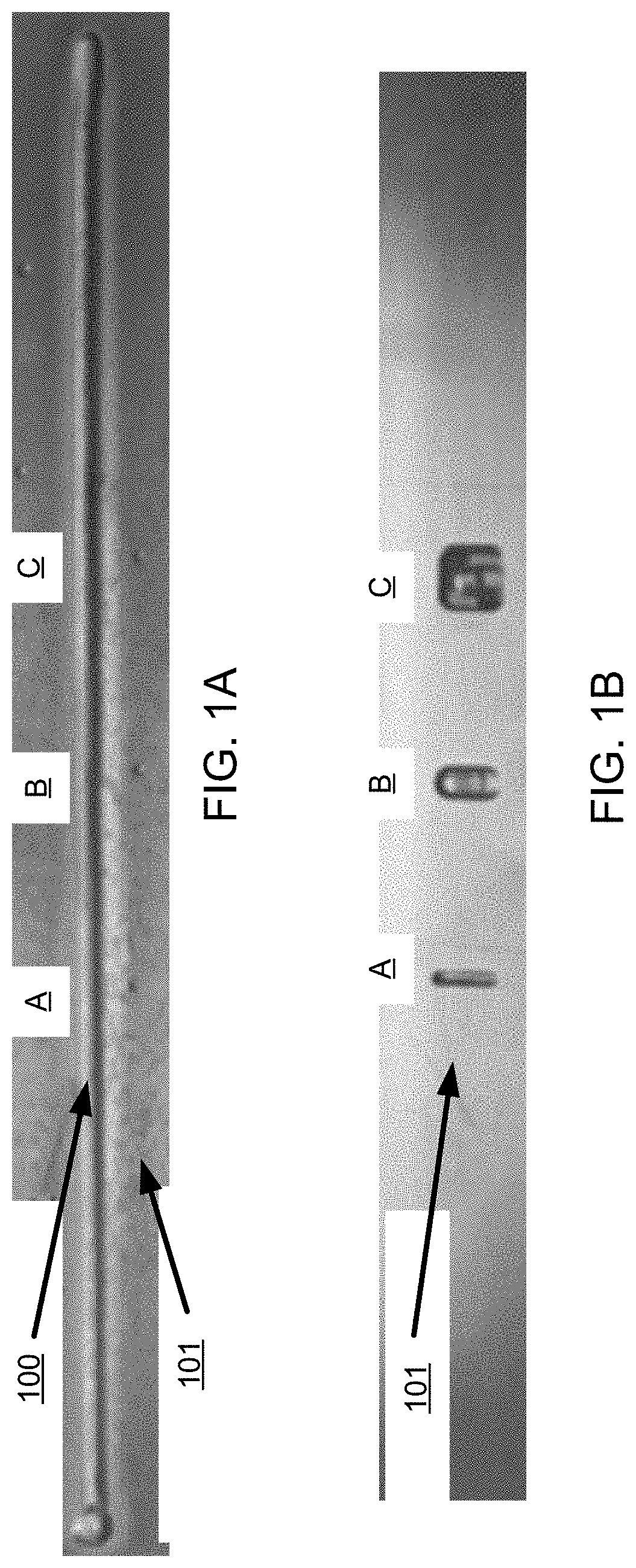
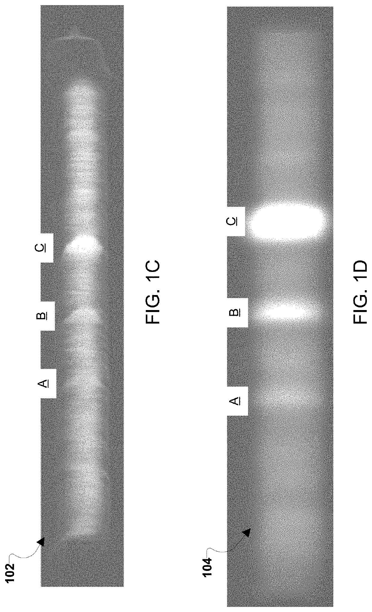
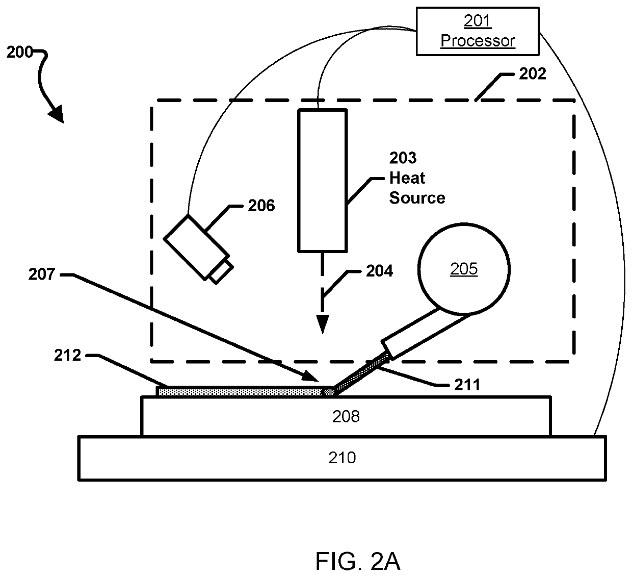
[0027]In an additive manufacturing process (also referred to as a 3-D printing process), thermal imaging may be used to monitor the quality of the build by measuring the temperature response and using that response to control the build settings. By monitoring the temperature distribution, the build quality may be determined and controlled using a feedback control system. In addition, flaws may be det...


PUM

PropertyMeasurementUnit
thicknessaaaaaaaaaa
thicknessesaaaaaaaaaa

Abstract

Systems and methods are provided for the real time inspection of additive manufacturing deposits using infrared thermography. Various embodiments may enable the measurement of material properties and the detection of defects during the additive manufacturing process. Various embodiments may enable the characterization of deposition quality, as well as the detection of deposition defects, such as voids, cracks, disbonds, etc., as a structure is manufactured layer by layer in an additive manufacturing process. Various embodiments may enable quantitative inspection images to be archived and associated with the manufactured structure to document the manufactured structure's structural integrity.

Description

CROSS-REFERENCE TO RELATED PATENT APPLICATION(S)[0001]This patent application claims the benefit of and priority to U.S. Provisional Patent No. 62 / 323,323, filed on Apr. 15, 2016, the contents of which are hereby incorporated by reference in its entirety.STATEMENT REGARDING FEDERALLY SPONSORED RESEARCH OR DEVELOPMENT[0002]The invention described herein was made in the performance of work under a NASA contract and by employees of the United States Government and is subject to the provisions of Public Law 96-517 (35 U.S.C. § 202) and may be manufactured and used by or for the Government for governmental purposes without the payment of any royalties thereon or therefore. In accordance with 35 U.S.C. § 202, the contractor elected not to retain title.BACKGROUND OF THE INVENTION[0003]Additive manufacturing, also referred to as three-dimensional printing (3-D printing), is a rapidly growing technology with numerous applications, from fabrication of space components to rapid production of a...

Claims


Application Information

Patent Timeline
Patent Type & Authority Patents(United States)
IPC IPC(8): B22D23/00B33Y10/00B33Y30/00B33Y50/02B22F3/115B22D46/00
CPCB22D23/003B22D46/00B22F3/115B33Y10/00B33Y30/00B33Y50/02B29C64/393Y02P10/25B22F10/85B22F10/36B22F10/38B22F10/25B22F10/22B22F12/90
Inventor ZALAMEDA, JOSEPH N.BURKE, ERIC R.HAFLEY, ROBERT A.DOMACK, CHRISTOPHER S.
Owner NASA
Why Eureka
Try Eureka