Retractable leash device and method therefor

Active Publication Date: 2021-06-15
BURKHARDT GEORGE WAYNE
View PDF9 Cites 3 Cited by
  • Summary
  • Abstract
  • Description
  • Claims
  • Application Information

AI Technical Summary

Benefits of technology

[0013]In accordance with one embodiment of the present invention, a retractable leash device for control of an animal is disclosed, having a multitude of settable maximum leash extensions therefrom the device while providing complete leash retraction thereinto the device at each set maximum leash extension length. The retractable leash device includes a leash line, a reel, a housing, an axle, a spring, a maximum extension brake and a maximum extension brake control. The reel includes at least one sidewall and a hub affixed thereto the at least one sidewall; the housing includes a leash line outlet aperture; and the maximum extension brake includes a leash line arresting member. The leash line is wound, in part, on the reel about the hub and exits the housing through the aperture. The leash line is operable to connect to the animal. The reel is mounted therewithin the housing on the axle and biased by the spring to retract the leash line thereon the reel. The maximum extension brake is positioned adjacent to the reel and engageable the

Problems solved by technology

However, the conventional retractable leashes present an annoying and possibly dangerous problem in that when the brake is engaged, retraction of the leash line is disabled.
As a result, when the tethered animal comes closer to its keeper, the leash line will become slack and drag the ground thereby, becoming highly susceptible to being entangled in the animals legs and/or in other adjacent objects, such as plants, structures, equipment, etc.
More importantly, when using these retractable leashes, the operator or keeper is warned to not touch or hold onto the leash line when in use, as serious injury can happen.
In cases, the animal can suddenly bolt away from its keeper thus, abruptly over tensioning the line resulting in a hand being seriously injured with the possibility of finger(s) being pulled off.
I other cases, serious

Method used


Image

  • Retractable leash device and method therefor
  • Retractable leash device and method therefor
  • Retractable leash device and method therefor

Examples


Example

First Embodiment—FIG. 1 Through FIG. 10

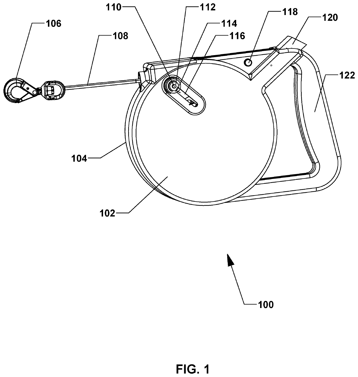
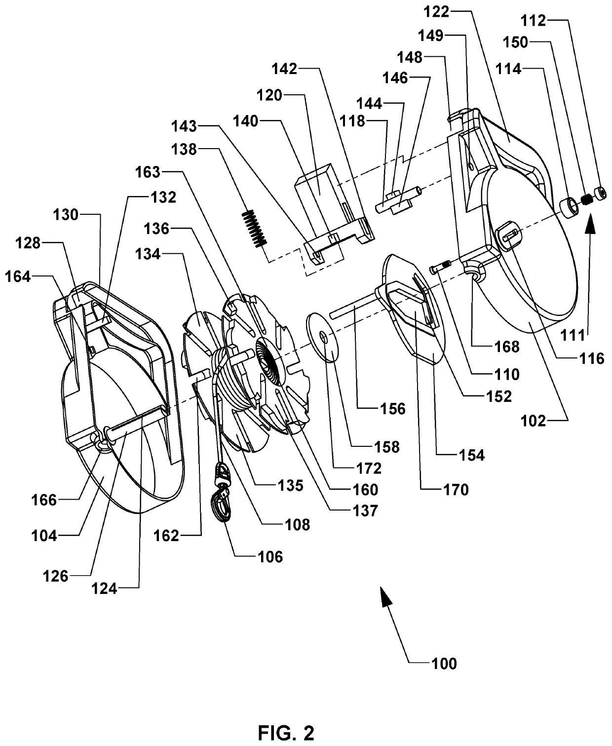
[0047]Referring to FIG. 1 and FIG. 2, a first embodiment 100 of the retractable leash device is shown with FIG. 1 depicting an assembled left side perspective view and FIG. 2 depicting an exploded left side perspective view. The first embodiment 100 includes a right side housing 104, a left side housing 102, a leash line connector 106, a leash line or leash 108, a leash line reel 134, a momentary brake control 120, a momentary brake control spring 138, a momentary brake locking pin or locking component 118, a maximum extension brake control assembly or a maximum extension brake control 111, a maximum extension brake 154, a reel constant force spring 160 and a reel spring cover 158.

[0048]The right side housing 104 includes a reel axle 126, reel spring slot 124, a right side momentary brake locking pin guide 164, a momentary brake spring beam 132, a right side momentary brake control guide 128, a right side leash line orifice half 166, a right si...

Example

Second Embodiment—FIG. 13 Through FIG. 20

[0075]Referring to FIG. 13 and FIG. 14, a second embodiment 200 of the retractable leash device is shown with FIG. 13 depicting an assembled right side perspective view and FIG. 14 depicting an exploded right side perspective view. The second embodiment 200 includes a right side housing 202, a left side housing 210, a leash line reel 224, a maximum extension brake 230, a combination momentary and maximum extension brake control 206, a brake control spring 232, a maximum extension brake locking pin or locking component 208, a leash line or leash 212, the leash line connector 106, a reel constant force spring 264, a reel spring cover 262 and a brake disengagement spring 260.

[0076]The right side housing 202 includes a reel axle 268 with slot similar to slot 124 for attachment of the inner end of the reel spring 264, a right side brake locking pin hole 270, a right side brake control guide 216, a brake spring beam 218, a right side leash line ori...

Example

Third Embodiment—FIG. 21 Through FIG. 30

[0096]Referring to FIG. 21, FIG. 22, FIG. 29 and FIG. 30, a third embodiment 300 of the retractable leash device is shown with FIG. 21 depicting an assembled right side perspective view; FIG. 22 depicting an exploded side perspective view; FIG. 29 depicting the maximum extension brake assembly in an expanded state; and FIG. 30 depicting the maximum extension brake assembly in a retracted state. The third embodiment 300 includes a right side housing 302, a left side housing 336, a leash line reel 306, a combination momentary and maximum extension brake control 322, a brake control spring 318, a maximum extension brake locking pin or locking component 330, a leash line or leash 350, the leash line connector 106, a constant force reel spring 348, a reel spring cover 346 and a maximum extension brake assembly or maximum extension brake 344,

[0097]The right side housing 302 includes a reel axle (not shown but the same as reel axles 126 and 268 of th...


PUM


Abstract

A retractable leash device for animal control is disclosed, having a multitude of settable maximum leash line extensions providing leash line retraction at each set extension length. The device includes a leash line connectable to an animal, a housing having an axle and an outlet aperture, a reel having a hub and mounted on the axle, a reel biasing spring to retract the leash line, a maximum extension brake having an arresting member and a brake control. The leash line is wound on the reel and exits the housing through the aperture. The arresting member crosses the leash line thereinbetween the hub and the aperture. Upon engagement of the brake therewith the reel and extension of the leash line, an eventual interaction of the arresting member therewith the leash line prevents further extension of the leash line. The brake control engages and disengages the brake with respect to the reel.

Description

CROSS-REFERENCE TO RELATED APPLICATIONS[0001]This application claims the benefit of U.S. Provisional Patent Application Ser. No. 62 / 748,510, filed Oct. 21, 2018 by the present inventor.FEDERALLY SPONSORED RESEARCH[0002]None.SEQUENCE LISTING[0003]None.BACKGROUNDField of Invention[0004]This application relates to a retractable leash device and method therefor and more specifically, to a retractable leash device and method therefor that can be set to various lengths of maximum leash line extensions and when set at a maximum extension length, complete leash line retraction and extension is enabled.Prior Art[0005]In order to maintain an animal, such as a dog, at a safe distance from its keeper, a hand held leash is normally employed and coupled to the animal via a collar, harness, an animal restraint device and the like. In the event that a leash having various leash line lengths is desired, a retractable leash is used having a spring biased reel serving to enable retraction and extensio...

Claims


Application Information

Patent Timeline
IPC IPC(8): A01K27/00B65H75/40B65H75/44B65H75/48
CPCA01K27/004B65H75/406B65H75/4436B65H75/486B65H75/4431B65H2701/35
Inventor BURKHARDT, GEORGE WAYNE
Owner BURKHARDT GEORGE WAYNE
Why Eureka
Try Eureka