
Portable extrication device and method of use

Inactive Publication Date: 2016-03-24
BRADBURY JASON
View PDF0 Cites 2 Cited by
  • Summary
  • Abstract
  • Description
  • Claims
  • Application Information

AI Technical Summary

Benefits of technology

The patent describes a patient transport conveyor that has a coupler for securely anchoring to a patient. The conveyor also has stabilizing feet and extendable lower legs that allow it to be used on uneven terrain or at varying angles. The feet pivot on an axis, allowing them to align with the ground for the most traction. The technical effects of this invention are improved stability and flexibility of the patient transport conveyor, making it easier to safely and securely transport patients in various situations.

Problems solved by technology

If it becomes necessary to extricate personnel from the pit, difficulties arise in safely and efficiently pulling the person up from the lower level.
Problems arise when persons who operate of one of these vehicles or are within such a pit must be safely removed from the vehicle or pit and lowered or raised to the ground for reasons such as injury, incapacitation, or other emergency situation.
Unfortunately these devices are generally not well designed to accommodate this type of use, are used infrequently and inconsistently by rescue personnel.
As such, these devices can be dangerous for both the injured operator and the emergency personnel attempting the rescue.
A number of challenges arise when lowering an injured person from an elevated position.
Numerous problems arise during such extrication.
First, the extrication litter must be pushed past the break over point of the elevated platform.
This process increases the risk of dropping the person in the basket to the ground, or accidently slamming them into a surface of whatever platform they are attempting to extricate the patient from.
Additionally, this process generally requires the rescuers to lean over the edge of the platform, and place undue, unnecessary, and even dangerous loads on the rescuers and on their bodies, along with creating a condition conducive to causing the rescuer to fall off the platform.

Method used


Image

  • Portable extrication device and method of use
  • Portable extrication device and method of use
  • Portable extrication device and method of use

Examples


Embodiment Construction

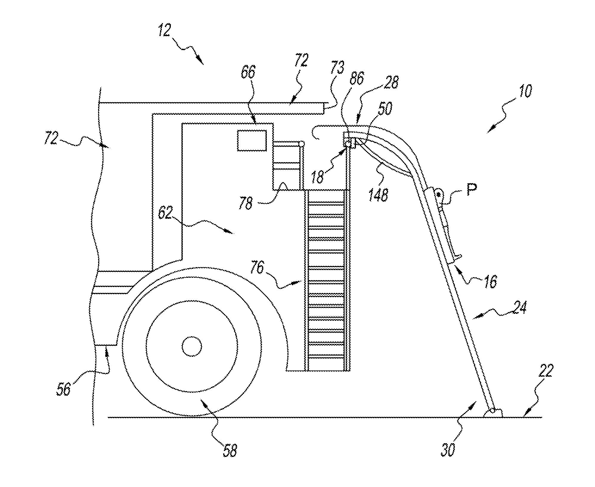
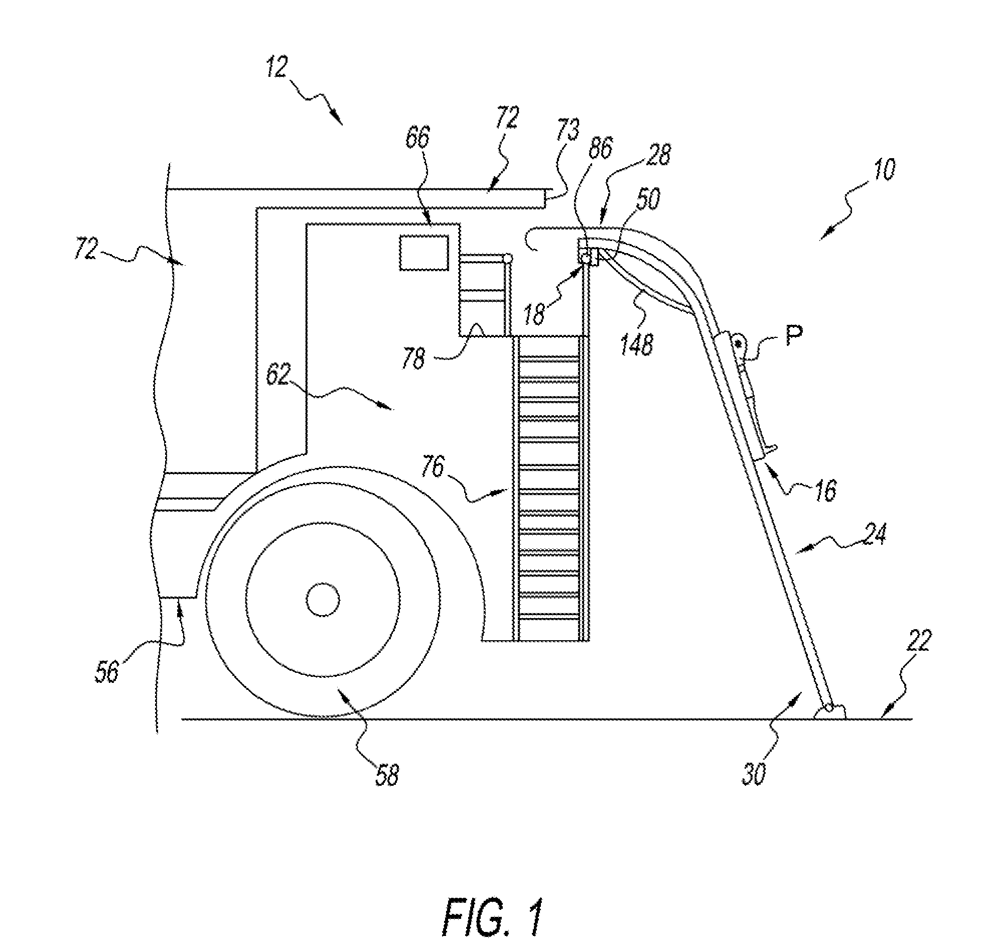
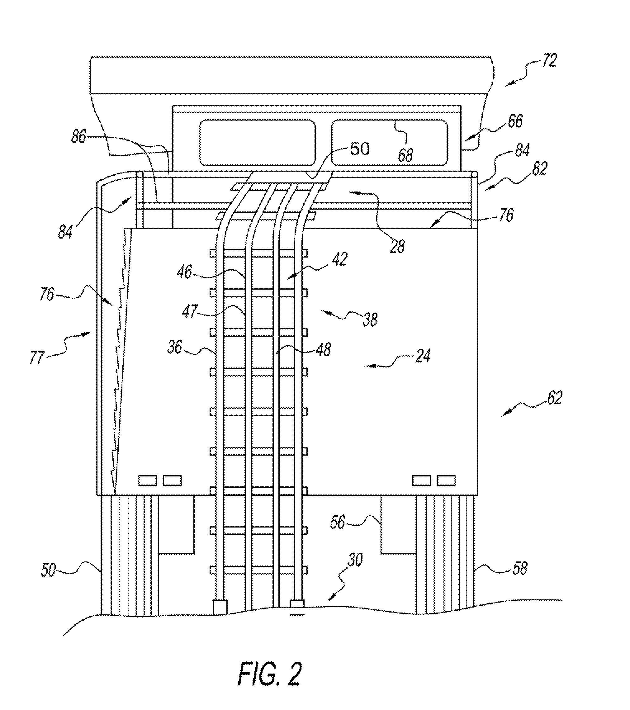
[0048]A patient transport conveyor is shown in the figures that is used for extrication from positions at a first elevation 18, such as the cab 66 of a mining vehicle such as a mining dump truck 12, or other type of vehicle, that has a location at a first elevation 18 from which the patient need to be removed from that is a second elevation 22 different than the first elevation 18.

[0049]Just as the first elevation 18 can be elevated relative to the second elevation 22 (the ground), the first elevation 18 can also be disposed below the second elevation 22, such as when the first elevation 18 is at the bottom of a pit or trench. Such elevational differences are quite common in all types of construction and building sites, including places such as mines, building sites, pits, trenches, excavations and the like.

[0050]The patient transport conveyor 10 is provided for transporting a patient P, and includes a bed portion usually upon which a patient can rest.

[0051]One example of such a lit...


PUM


Abstract

A patient transport conveyor for conveying a patient on a liner between a first elevation and a second elevation includes a rail containing conveyor having a first end for placement at the first elevation and a second end for placement at the second elevation. The rail containing conveyor includes first and second spaced generally parallel rail members extending generally between the first and second ends. The first and second rail members define a litter receiving space for receiving the litter and maintaining the litter on the conveyor. A guide member extends generally between the first and second ends. The guide member configured for being engaged with the litter to help maintain the litter in the litter receiving space. A coupler is disposed at the first end and is configured for coupling the transport conveyor to an anchoring at the first elevation for maintaining the position of the transport conveyor.

Description

PRIORITY CLAIM[0001]The instant application claims benefit of priority to U.S. Provisional Patent Application Number Ser. No. 62 / 0053,748 that was filed on Sep. 22, 2014, and which is fully incorporated herein by reference.TECHNICAL FIELD OF THE INVENTION[0002]The present invention is a device for safely and efficiently extricating an incapacitated or injured person from a higher or lower elevation position and a method for use.BACKGROUND OF THE INVENTION[0003]Mining, construction, and agricultural personnel use heavy equipment items such as dump trucks, cranes, earth movers, bull dozers, tractors, and combines to perform routine mining, construction, and agricultural related tasks. These large equipment items often require the operator to climb a set of stairs or ladders in order to ascend to the cab, or control center of the machinery item.[0004]For example, on a Caterpillar model 793 the operator must ascend a staircase that is affixed to the vehicle in order to reach the cab. Th...

Claims


Application Information

Patent Timeline
IPC IPC(8): A61G3/06A61G3/02B66B9/187
CPCA61G3/063A61G3/0263B66B9/187A61G1/007A62B1/02
Inventor BRADBURY, JASON
Owner BRADBURY JASON
Learn More