Ophthalmic lens comprising lenslets for preventing and/or slowing myopia progression

a technology of ophthalmic lenses and lenslets, which is applied in the field of ophthalmic lenses, can solve the problems of hyperopia, eye growth is not good enough, and the eye is not growing fast enough, so as to achieve better distance vision correction

Active Publication Date: 2021-07-13
JOHNSON & JOHNSON VISION CARE INC
View PDF28 Cites 0 Cited by
  • Summary
  • Abstract
  • Description
  • Claims
  • Application Information

AI Technical Summary

Benefits of technology

[0014]The ophthalmic lens with positive defocus, lenslets of the present invention overcomes the limitations of the prior art by ensuring better distance vision correction without compromising visual acuity and contrast sensitivity.
[0015]In accordance with one aspect, the present invention is directed to an ophthalmic lens for at least one of slowing, retarding or preventing myopia progression. The ophthalmic lens comprising a front convex surface, a back concave surface, an optic zone including primary base sphere distance correction zones and a plurality of lenslets with add power interspersed between and adjacent to the primary base sphere distance correction zones, the primary base sphere correction zones create a wave-front that focuses at a single point along a primary optical axis of the ophthalmic lens and on the retina of an eye, and the plurality of lenslets with add power create non-coaxial wave-fronts that focus in front of the retina along their own optical axis that is different from the primary optical axis, the combination of lenslets and primary distance correction zones being arranged to provide clear vision and myopic defocus to all regions of the retina, wherein the ophthalmic lens is selected from the group consisting of spectacle lenses, intraocular lenses, and corneal inlays and onlays.
[0017]One way to achieve improved treatment efficacy is to design non-coaxial optics that enhance the impact of myopic blur in regulating eye growth without interfering with foveal image quality. With such designs, for each diopter of myopic defocus the retinal image quality is less degraded at the fovea and the focus of both sagittal and tangential powers are in front of the retina. An ophthalmic lens design with plano or negative distance power that provides optimal refractive correction, along with small islands of positive defocus, non-coaxial lenslets (myopic defocus zones) with local powers ranging from +1.00 to +30.00D, arranged in an optimal pattern and covering about twenty (20) to eighty (80) percent of the optical zone and / or central pupil area to deliver positive foci of light in front of the retina, with low impact on foveal image quality while slowing down the rate of myopia progression. The optimal pattern may comprise a circular or hexagon arrangement, a radial arrangement, an equally spaced or non-equally spaced arrangement, or any suitable arrangement, including combinations of the above arrangements.
[0021]The prevalence of myopia, including high myopia, is increasing at an unprecedented rate throughout the world. The contact lens design of the present invention provides a simple, cost-effective and efficacious means and method for preventing and / or slowing myopia progression which, may help decrease the rate of high myopia. The lenses of the present invention are made from the same lens material as currently manufactured lenses utilizing the same manufacturing processes. Only the mold surfaces would be changed to incorporate the additional powers for the lenslets.

Problems solved by technology

Myopia typically develops because the axial length of the eye grows to be longer than the focal length of the optical components of the eye, that is, the eye grows too long.
Hyperopia typically develops because the axial length of the eye is too short compared with the focal length of the optical components of the eye, that is, the eye does not grow enough.
High myopia is also associated with an increased risk of retinal disease, cataract, and glaucoma.
However, the corrective approach to the conditions does not address the cause of the condition, but is merely prosthetic or for treating the symptoms of the condition.
Most eyes do not have simple myopia or hyperopia, but may also have more complex optical errors such as myopic astigmatism or hyperopic astigmatism.
Blur with positive lenses, which leads to myopic blur and a decrease in scleral growth rate, results in the development of hyperopic refractive errors.
Blur with negative lenses, which leads to hyperopic blur and an increase in scleral growth rate, results in development of myopic refractive errors.

Method used


Image

  • Ophthalmic lens comprising lenslets for preventing and/or slowing myopia progression
  • Ophthalmic lens comprising lenslets for preventing and/or slowing myopia progression
  • Ophthalmic lens comprising lenslets for preventing and/or slowing myopia progression

Examples


Embodiment Construction

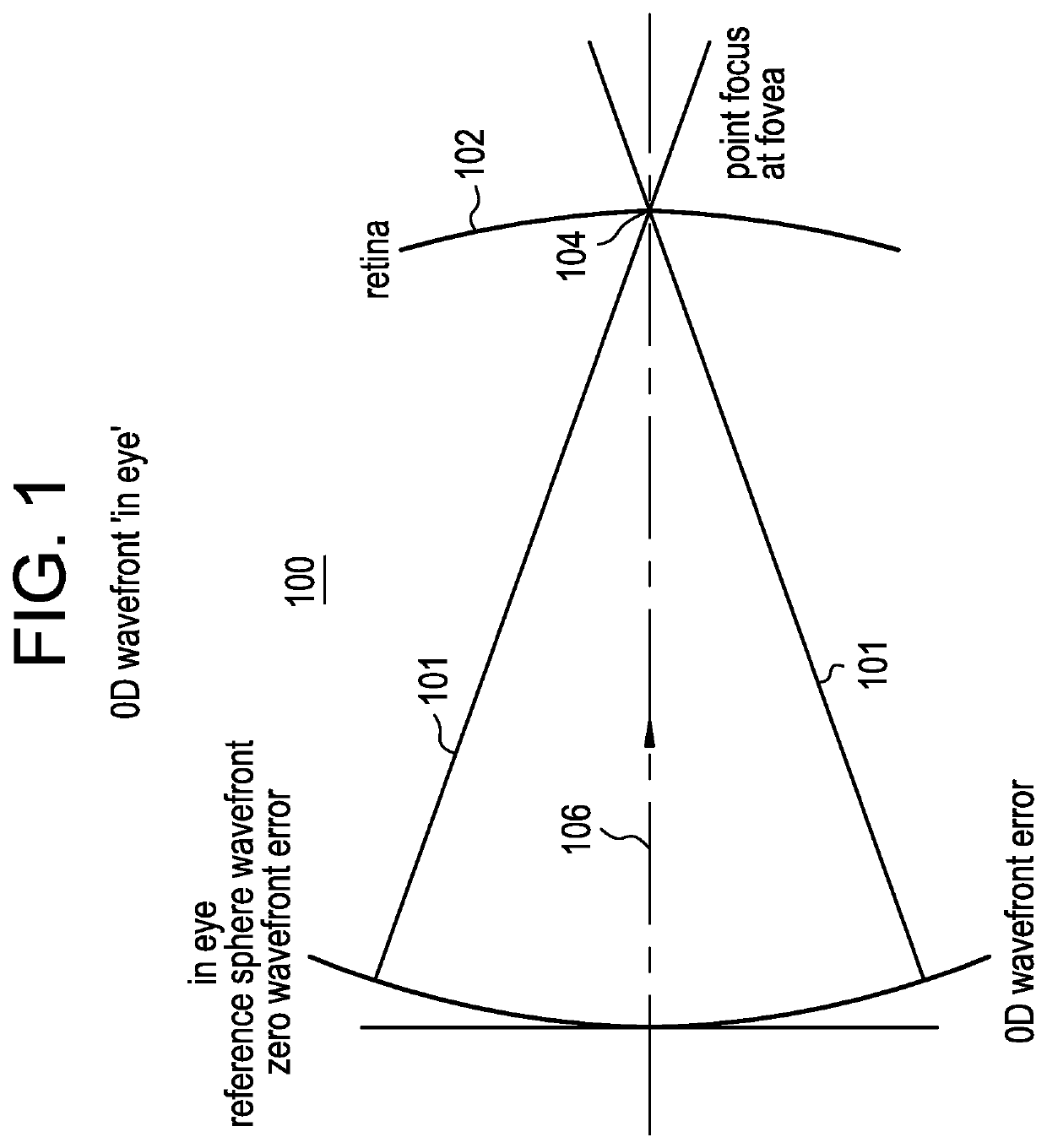
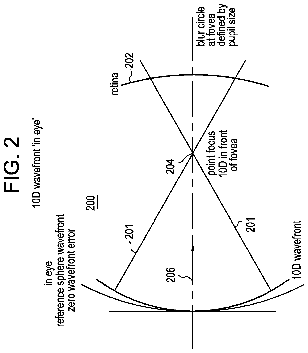
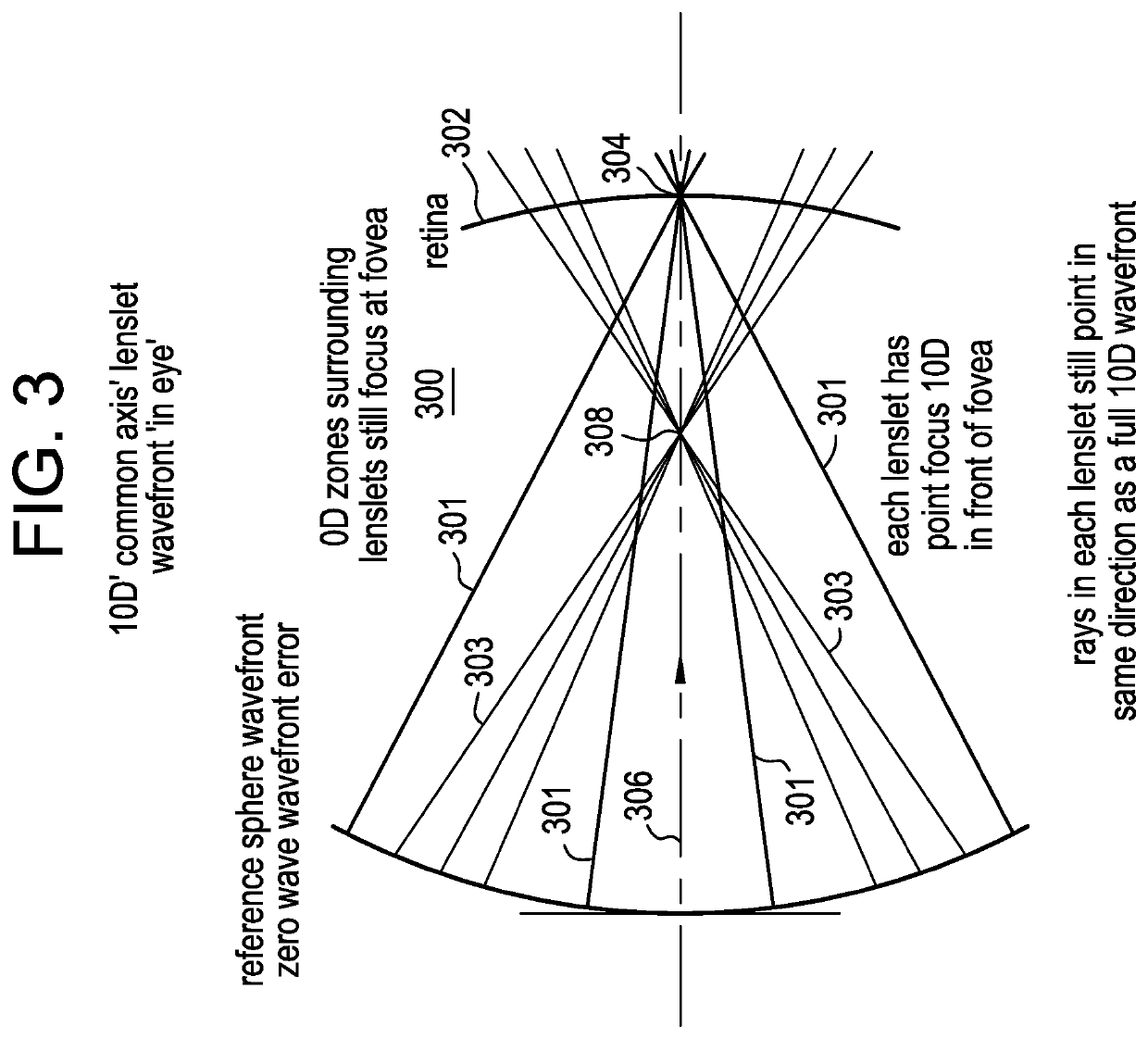
[0039]Experiments have shown that the eyes respond to hyperopic defocus that leads to axial elongation, therefore delivering higher plus powers to the central retina should slow myopia progression. However, just delivering higher plus power to the central retina may have a deleterious effect on vision. Accordingly, an ophthalmic lens, for example, a contact lens with negative base power that provides optimal refractive correction for distance in combination with small areas or islands of positive power (lenslets) arranged in a particular pattern to deliver positive foci of light in front of the retina will provide the myopic defocus to inhibit myopia progression without impacting visual acuity and contrast sensitivity.

[0040]The present invention comprises an ophthalmic lens for at least one of slowing, retarding or preventing myopia progression. The ophthalmic lens includes, within its primary optical zone, multiple non-coaxial plus power zones. Each non-coaxial plus power zone is a...


PUM


Abstract

Contact lenses incorporating an array of non-coaxial lenslets with add power that create non-coaxial myopic defocus within the optic zone of the lens may be utilized to prevent and / or slow myopia progression. The positive, non-coaxial lenslets cover about twenty to eighty percent of the central pupil area to deliver positive foci of light in front of the retina to slow the rate of myopia progression.

Description

CROSS REFERENCE TO RELATED APPLICATION[0001]The present application is a Continuation-in-Part of U.S. patent application Ser. No. 14 / 747,166 filed on Jun. 23, 2015.BACKGROUND OF THE INVENTION1. Field of the Invention[0002]The present invention relates to ophthalmic lenses, for example, single vision and / or astigmatic lenses, and more particularly, to contact lenses, intra-ocular lenses, corneal inlays / onlays and / or spectacles lenses designed to slow, retard or prevent myopia progression. The ophthalmic lenses of the present invention comprise positive, non-coaxial lenslets that provide, at any vergence distance, a myopia progression stop signal throughout the central, near and far periphery of the retina for preventing and / or slowing myopia progression while maintaining clear central vision.2. Discussion of the Related Art[0003]Common conditions which lead to reduced visual acuity are myopia and hyperopia, for which corrective lenses in the form of spectacles, or rigid or soft conta...

Claims


Application Information

Patent Timeline
Patent Type & Authority Patents(United States)
IPC IPC(8): G02C7/04G02C7/08G02C7/02
CPCG02C7/049G02C7/041G02C7/081G02C7/086G02C7/024G02C2202/24G02C7/02G02C7/06G02C7/08G02C7/04G02C7/022G02C7/044G02C2202/12
Inventor LAU, MANWAI CHARISBRENNAN, NOELCHEHAB, KHALEDCHENG, XUCOLLINS, MICHAELDAVIS, BRETTRITCHEY, ERIC R.YI, FAN
Owner JOHNSON & JOHNSON VISION CARE INC
Why Eureka
Try Eureka