Unlock instant, AI-driven research and patent intelligence for your innovation.

Lens apparatus and imaging apparatus

a technology of lens and zoom operation ring, which is applied in the direction of mountings, instruments, camera body details, etc., can solve the problems of difficult to increase the rotation angle of the zoom operation ring, difficult to provide a plurality of cams, and difficult to increase the rotation angle of the cam barrel

Active Publication Date: 2021-07-27
CANON KK
View PDF6 Cites 0 Cited by
  • Summary
  • Abstract
  • Description
  • Claims
  • Application Information

AI Technical Summary

Benefits of technology

The present invention is about a lens apparatus that includes multiple lens holders with a wide rotation angle of the operation ring. The lens apparatus also includes a first cam barrel, a second cam barrel, and a third cam barrel. The first cam barrel is located outside of the second and third cam barrels. When the first cam barrel is rotated by a certain angle, the second and third cam barrels also rotate by a certain angle. This rotation angle is determined by a specific formula. The technical effect of this invention is to improve the accuracy and stability of the lens apparatus during use.

Problems solved by technology

However, the lens barrel disclosed in Japanese Patent Laid-Open No. 2015-106128 needs a cam barrel having a plurality of cam grooves, and has difficulties in increasing the rotation angle of the cam barrel.
It is therefore difficult to increase the rotation angle of the zoom operation ring.
The lens barrel disclosed in Japanese Patent No. 5962432 has difficulties in providing a plurality of cams, for example, in operating a plurality of (five or more) units (or a plurality of lens holders).

Method used


Image

  • Lens apparatus and imaging apparatus
  • Lens apparatus and imaging apparatus
  • Lens apparatus and imaging apparatus

Examples


Embodiment Construction

[0015]Referring now to the accompanying drawings, a description will be given of embodiments according to the present invention.

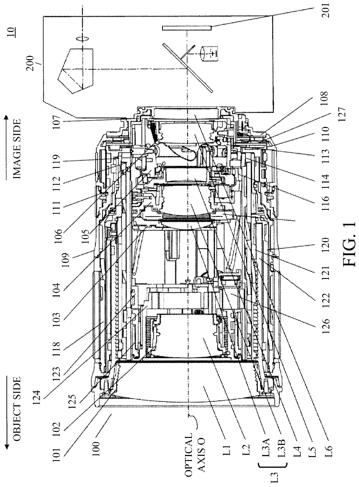
[0016]Referring now to FIGS. 1 to 4, a description will be given of a lens apparatus and an imaging apparatus according to this embodiment. FIGS. 1 and 2 are sectional views of an imaging apparatus 10 taken along a plane parallel to an optical axis O. FIG. 1 illustrates the interchangeable lens (lens apparatus) 100 located at the wide-angle end, and FIG. 2 illustrates the interchangeable lens 100 located at the telephoto end. FIG. 3 is an exploded perspective view of the interchangeable lens 100. FIG. 4 is an exploded perspective view of an area A enclosed by a broken line in FIG. 3. However, for better understandings, FIGS. 3 and 4 omit members unnecessary for the description of this embodiment.

[0017]The imaging apparatus 10 is a single-lens reflex camera system that includes a camera body 200 and an interchangeable lens 100 attachable to and detachable fr...


PUM


Abstract

A lens apparatus includes a plurality of lens holders, a first cam barrel, a second cam barrel, and a third cam barrel each having a cam groove configured to move at least one of the plurality of lens holders in an optical axis direction. The first cam barrel is located outside the second cam barrel and the third cam barrel, and the second cam barrel is located outside the third cam barrel. A predetermined condition is satisfied.

Description

BACKGROUND OF THE INVENTIONField of the Invention[0001]The present invention relates to a lens apparatus and an imaging apparatus.Description of the Related Art[0002]Japanese Patent Laid-Open No. 2015-106128 discloses a compact lens barrel having a wide focal length. Japanese Patent No. 5962432 discloses a lens barrel that includes a drive barrel, changes rotation angles of a zoom operation ring and a cam barrel relative to a guide barrel, and increases the rotation angle of the zoom operation ring while reducing the rotation angle of the cam barrel. This configuration can arrange a plurality of cam grooves on a cam barrel while improving the rotation detection accuracy of the zoom operation ring.[0003]However, the lens barrel disclosed in Japanese Patent Laid-Open No. 2015-106128 needs a cam barrel having a plurality of cam grooves, and has difficulties in increasing the rotation angle of the cam barrel. It is therefore difficult to increase the rotation angle of the zoom operation...

Claims


Application Information

Patent Timeline
Patent Type & Authority Patents(United States)
IPC IPC(8): G02B7/02
CPCG02B7/02G02B7/10G03B17/12G03B2205/0046
Inventor SASAKI, KUNIHIKO
Owner CANON KK