
Method and apparatus for substantially artifact-free anatomic positioning

an anatomical positioning and substantially artifact-free technology, applied in the field of anatomical positioning, can solve the problems of affecting the proximity of metallic components to the imaging array, affecting the field uniformity of the magnetic imaging array, and causing catastrophic and lethal mishaps

Active Publication Date: 2021-08-03
CAMPAGNA MICHAEL +1
View PDF21 Cites 0 Cited by
  • Summary
  • Abstract
  • Description
  • Claims
  • Application Information

AI Technical Summary

Problems solved by technology

In the field of radiographic and magnetic medical imaging, the proximity of metallic components to the imaging array can be detrimental as metals are a prime source of imaging distortion and degradation, referred to herein as artifact.
Within the MRI environment, the presence of ferromagnetic metals can lead to catastrophic and lethal mishaps due to the action of the extremely powerful imaging magnets acting upon ferromagnetic implements within the environment, which may attract said ferromagnetic objects at high velocities transforming them into projectiles.
Non-ferromagnetic metals within proximity to a magnetic imaging array can cause distortion of field uniformity in the magnetic imaging array.
It is believed that this distortion of field uniformity can cause artifacts that may render the images obtained as clinically unusable.
In the field of radiographic imaging, the presence of ferromagnetic and non-ferromagnetic metals in proximity to the imaging apparatus can result in a streak artifacts.
One can expect that streak artifacts may degrade the quality of clinical and diagnostic medical images and may render these images clinically unusable.
It is believed that currently available radiolucent positioners that provide variable positioning with or without locking means utilize metal components, typically non-ferromagnetic, in their construction for strength, which may result in the appearance of metallic artifacts in the images which are produced.
In view of the foregoing, it is clear that these traditional techniques are not perfect and leave room for more optimal approaches.

Method used


Image

  • Method and apparatus for substantially artifact-free anatomic positioning
  • Method and apparatus for substantially artifact-free anatomic positioning
  • Method and apparatus for substantially artifact-free anatomic positioning

Examples


Embodiment Construction

[0016]The present invention is best understood by reference to the detailed figures and description set forth herein.

[0017]Embodiments of the invention are discussed below with reference to the Figures. However, those skilled in the art will readily appreciate that the detailed description given herein with respect to these figures is for explanatory purposes as the invention extends beyond these limited embodiments. For example, it should be appreciated that those skilled in the art will, in light of the teachings of the present invention, recognize a multiplicity of alternate and suitable approaches, depending upon the needs of the particular application, to implement the functionality of any given detail described herein, beyond the particular implementation choices in the following embodiments described and shown. That is, there are numerous modifications and variations of the invention that are too numerous to be listed but that all fit within the scope of the invention. Also, ...


PUM


Abstract

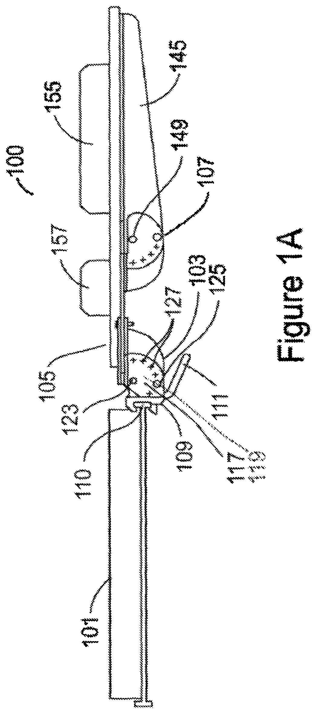
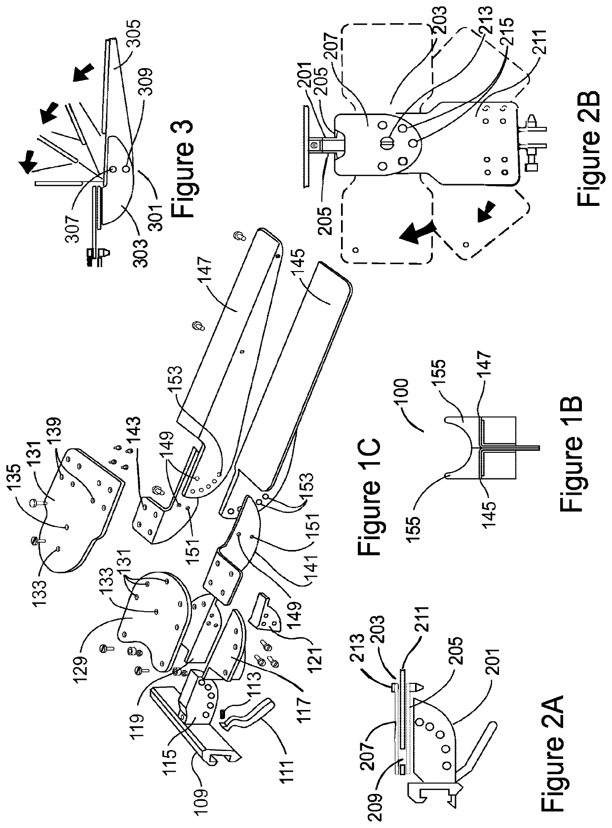
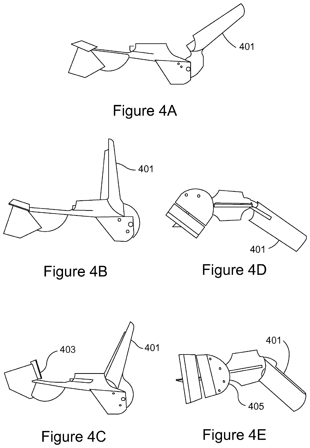
A technique of forming a joint employing laminar sheeting is provided. At least a portion of the laminar sheeting includes a material that is substantially artifact-free such that the joint causes little imaging artifacts when medically imaged over at least a portion of the laminar sheeting including the rotational axis of said joint, which is at least useful for variable angular articulation of at least one anatomic supporting member joined to the joint and the normal anatomic positioning of at least one anatomic supporting member during normal anatomic positioning use.

Description

CROSS-REFERENCE TO RELATED APPLICATIONS[0001]The present Utility patent application claims priority benefit of the U.S. provisional application for patent Ser. No. 61 / 389,271 filed on 3 Oct. 2010 under 35 U.S.C. 120 and entitled “Method and Apparatus for Achieving Variable Radiolucent Anatomic Positioning Via the Usage of Non Metallic, Articulating, Variably Positioning, an Lockable Interconnecting Radiolucent Joints”, under 35 U.S.C. 119(e). The contents of this related provisional application are incorporated herein by reference for all purposes to the extent that such subject matter is not inconsistent herewith or limiting hereof.FEDERALLY SPONSORED RESEARCH OR DEVELOPMENT[0002]Not applicable.REFERENCE TO SEQUENCE LISTING, A TABLE, OR A COMPUTER LISTING APPENDIX[0003]Not applicable.COPYRIGHT NOTICE[0004]A portion of the disclosure of this patent document contains material that is subject to copyright protection. The copyright owner has no objection to the facsimile reproduction b...

Claims


Application Information

Patent Timeline
Patent Type & Authority Patents(United States)
IPC IPC(8): A61B6/04A61B5/055
CPCA61B6/04A61B5/055
Inventor CAMPAGNA, MICHAEL
Owner CAMPAGNA MICHAEL
Learn More