Pneumatic tire

a pneumatic tire and tire circumferential technology, applied in the field of pneumatic tires, can solve the problems of increasing the rigidity difference between the end portions of the partial land portion the so as to achieve the effect of suppressing uneven wear in the circumferential direction of the tire and improving drainage performan

Active Publication Date: 2021-08-17
TOYO TIRE & RUBBER CO LTD
View PDF12 Cites 0 Cited by
  • Summary
  • Abstract
  • Description
  • Claims
  • Application Information

AI Technical Summary

Benefits of technology

[0005]In this case, since the partial land portion has the configuration in which an end portion on one side in the tire circumferential direction is relatively wide, whereas an end portion on the other side in the tire circumferential direction is relatively narrow, the rigidity of the end portion on one side becomes relatively high and the rigidity of the end portion on the other side becomes relatively low. As a result, the rigidity difference between both end portions of the partial land portion in the tire circumferential direction is increased, and uneven wear in the tire circumferential direction is increased.
[0022]According to the present invention, uneven wear in the tire circumferential direction can be suppressed in a pneumatic tire having improved drainage performance due to the formation of a circumferential direction sipe extending in a direction slanting toward the tire circumferential direction in the land portion.

Problems solved by technology

As a result, the rigidity difference between both end portions of the partial land portion in the tire circumferential direction is increased, and uneven wear in the tire circumferential direction is increased.

Method used


Image

  • Pneumatic tire
  • Pneumatic tire
  • Pneumatic tire

Examples


Embodiment Construction

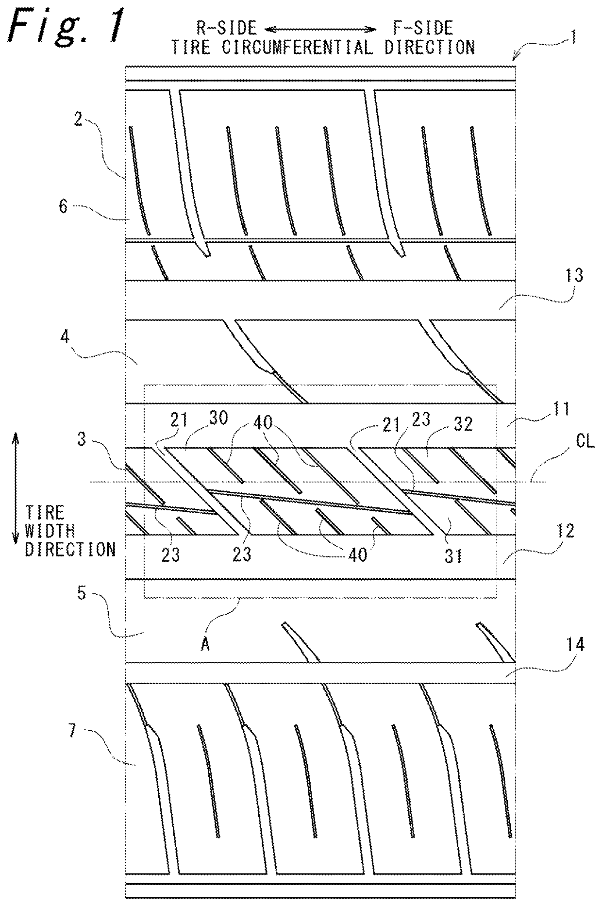
[0032]In the following, an embodiment according to the present invention will be described with reference to the accompanying drawings. It should be noted that the following description is, fundamentally, merely illustrative and is not intended to limit the present invention, products to which the present invention is applied, or applications of the present invention. In addition, the drawings are schematic, and the ratio and the like of each dimension are different from actual ones.

[0033]FIG. 1 is a plan view showing a developed tread pattern of a tread portion 2 of a pneumatic tire 1 according to an embodiment of the present invention. It should be noted that for convenience of explanation, the direction toward the right side in the drawing in the tire circumferential direction is referred to as F side, and the direction toward the left side in the drawing is referred to as R side.

[0034]As shown in FIG. 1, four main grooves 11 to 14 extending in the tire circumferential direction ...


PUM


Abstract

A pneumatic tire includes a land portion having a circumferential direction sipe extending in a direction inclined with respect to the tire circumferential direction, a partial land portion positioned on at least one of the land portion partitioned with the circumferential direction sipe, and a plurality of cross sipes extending in a direction intersecting with the circumferential direction sipe in the partial land portion. The partial land portion includes a wide end portion and a narrow end portion. The plurality of cross sipes include a wide portion sipe located closest to a wide end of the partial land portion, and a narrow portion sipe located closest to a narrow end of the partial land portion. The wide portion sipe has a distal end positioned in a sipe projection portion, and the narrow portion sipe has a distal end positioned in a non-sipe projection portion.

Description

CROSS-REFERENCE TO RELATED APPLICATIONS[0001]This application claims priority of Japanese Patent Application No.: 2017-88811 filed on Apr. 27 2017, the content of which is incorporated herein by reference.BACKGROUND OF THE INVENTIONTechnical Field[0002]The present invention relates to a pneumatic tire.Related Art[0003]It is known that in a pneumatic tire including land portions (for example, ribs) partitioned with plurality of main grooves extending in a tire circumferential direction, forming circumferential direction sipes extending in a direction slanting toward the tire circumferential direction in the land portions increases the groove volume to improve drainage performance (for example, see Japanese Unexamined Patent Application Publication No. 2014-162295).SUMMARY[0004]However, when the circumferential direction sipes are slanted toward the tire circumferential direction, partial land portions partitioned in the tire width direction with the circumferential direction sipes ha...

Claims


Application Information

Patent Timeline
Patent Type & Authority Patents(United States)
IPC IPC(8): B60C11/12B60C11/03
CPCB60C11/1236B60C11/0304B60C11/0306B60C11/12B60C2011/1209B60C2011/1245B60C2011/1254B60C11/032B60C2011/0341B60C2011/0388
Inventor KAMADA, NOBUYUKI
Owner TOYO TIRE & RUBBER CO LTD
Why Eureka
Try Eureka