Steering control device

a control device and steering technology, applied in the direction of electric steering, power driven steering, vehicle components, etc., can solve the problems of reducing the value of the vehicle state quantity, the steering reaction force may not be appropriately compensated, and the grip state cannot be accurately determined.

Active Publication Date: 2021-08-24
JTEKT CORP
View PDF16 Cites 0 Cited by
  • Summary
  • Abstract
  • Description
  • Claims
  • Application Information

AI Technical Summary

Benefits of technology

[0009]The disclosure provides a steering control device that can provide a superior steering feeling. The disclosure provides a steering control device that can apply an appropriate steering reaction force according to a grip state.
[0055]With this configuration, when the traveling state quantity represents the intermediate-to-high speed state, the grip state quantity is calculated at the distribution proportions including only the second grip component, that is, without using the first grip component based on the ideal axial force and the road-surface axial force. With the above-described configuration, since the second grip component is a value based on the vehicle state quantity axial force which has high accuracy in the intermediate-to-high speed state of the vehicle and is not based on the ideal axial force of which the accuracy decreases in the intermediate-to-high speed state of the vehicle, the grip state quantity can be more appropriately calculated.

Problems solved by technology

As a result, when the grip state is determined based on the difference between the road-surface axial force and the ideal axial force, there is a possibility that the grip state may not be accurately determined, and the steering reaction force may not be appropriately compensated for.
However, when the traveling state of the vehicle represents the low-speed state including the stopped state, the value of the vehicle state quantity decreases, and therefore, the magnitude of noise relative to the output value of a sensor that detects the vehicle state quantity increases relatively.

Method used


Image

  • Steering control device
  • Steering control device
  • Steering control device

Examples


first embodiment

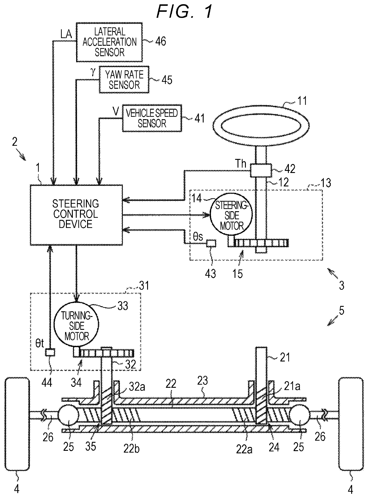
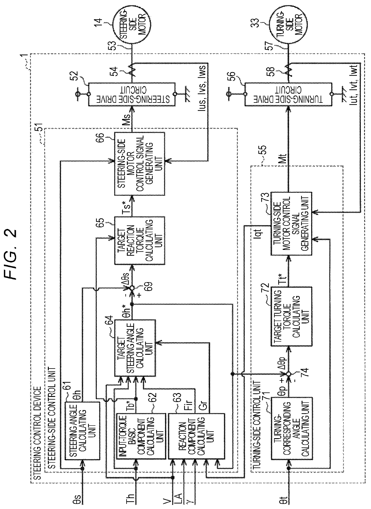
[0210]The configuration of the steering control device 1 will be described below in detail. As illustrated in FIG. 14, the steering control device 1 includes a steering-side control unit 51 serving as a control unit that outputs a steering-side motor control signal Ms and a steering-side drive circuit 52 that supplies a drive power to a steering-side motor 14 based on the steering-side motor control signal Ms. Current sensors 54 that detect phase current values Ius, Ivs, and Iws of the steering-side motor 14 which flow in connection lines 53 between the steering-side drive circuit 52 and motor coils of phases of the steering-side motor 14 are connected to the steering-side control unit 51. In FIG. 14, for the purpose of convenience of description, the connection lines 53 of the phases and the current sensors 54 of the phases are collectively illustrated as being single. The same elements as the elements of the first embodiment illustrated in FIG. 2 will be referred to by the same re...

second embodiment

[0234]The reaction component calculating unit 63 calculates a reaction component Fir (an adjusted distributed axial force) adjusted based on the grip state quantity Gr similarly to the Accordingly, the target steering angle θh* is changed and the target reaction torque Ts* is changed.

[0235]In this embodiment, the same operations and advantages as the operations and advantages of (1) to (6) in the second embodiment are achieved.

[0236]Hereinafter, a steering control device according to a fourth embodiment will be described with reference to the accompanying drawings. For the purpose of convenience of description, the same elements as the elements of the second embodiment will be referred to by the same reference numerals and signs and description thereof will not be repeated.

[0237]As illustrated in FIG. 20, the steering-side control unit 51 according to this embodiment includes a target turning-corresponding angle calculating unit 521 that calculates a target turning-corresponding an...

sixth embodiment

[0309]Similarly to the sixth embodiment, the calculated grip state quantity Gr is input to the adjustment gain calculating unit 68 and the target reaction torque Ts* is changed according to the grip state by changing the first to fourth adjustment gains K1 to K4.

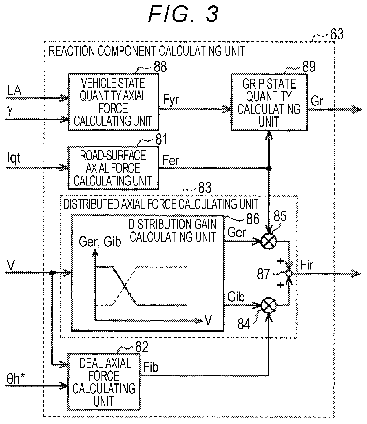
[0310]Operations and advantages of this embodiment will be described below. In this embodiment, the following advantages are achieved in addition to the operations and advantages of (1) and (3) in the sixth embodiment. (4) When at least one of the lateral acceleration LA and the vehicle speed V indicates that the vehicle is in the low-speed state, the grip state quantity calculating unit 89 calculates the grip state quantity Gr at the distribution proportions including only the first grip component Gr1 based on the ideal axial force Fib, that is, without using the second grip component Gr2 based on the vehicle state quantity axial force Fyr. Since the first grip component Gr1 is a value based on the ideal axial force Fib wit...


PUM


Abstract

A steering control device includes a control unit, and the control unit includes a target steering angle calculating unit configured to calculate a target steering angle based on a steering torque and is configured to calculate a target reaction torque based on execution of feedback control for causing the steering angle to match the target steering angle. The control unit includes a plurality of axial force calculating units configured to calculate a plurality of kinds of axial forces acting on a turning shaft based on different state quantities and a grip state quantity calculating unit configured to calculate a grip state quantity based on the plurality of kinds of axial forces. The target steering angle calculating unit is configured to calculate the target steering angle in consideration of the grip state quantity.

Description

INCORPORATION BY REFERENCE[0001]The disclosure of Japanese Patent Application No. 2018-106409 filed on Jun. 1, 2018, Japanese Patent Application No. 2018-106410 filed on Jun. 1, 2018, and Japanese Patent Application No. 2018-106411 filed on Jun. 1, 2018, each including the specification, drawings and abstract, is incorporated herein by reference in its entirety.BACKGROUND1. Technical Field[0002]The disclosure relates to a steering control device.2. Description of Related Art[0003]Electric power steering systems (EPS) using a motor as a drive source have been widely employed as steering systems for vehicles. A steering control device configured to control an EPS as a control object may execute various compensation controls to improve a steering feeling. For example, Japanese Unexamined Patent Application Publication No. 2009-40341 (JP 2009-40341 A) discloses that a grip state of tires (for example, a degree of grip loss indicating a degree of loss of grip of tires) is detected and an...

Claims


Application Information

Patent Timeline
Patent Type & Authority Patents(United States)
IPC IPC(8): B62D5/04B62D5/00
CPCB62D5/046B62D5/003B62D5/006B62D5/0481B62D5/04B62D6/00B62D1/04B62D6/008
Inventor KODERA, TAKASHI
Owner JTEKT CORP
Why Eureka
Try Eureka