
Holster system with removable sight cover

a sight cover and holster technology, applied in the field of holster systems with removable sight covers, can solve the problems of high cost of injection molding molding molds, and achieve the effect of quick removal and/or replacemen

Active Publication Date: 2021-08-31
VISTA OUTDOOR OPERATIONS
View PDF56 Cites 1 Cited by
  • Summary
  • Abstract
  • Description
  • Claims
  • Application Information

AI Technical Summary

Benefits of technology

[0011]A feature and benefit of embodiments is a holster system including one or more rear sight covers that can be quickly removed and / or replaced on a holster and that when attached are secure on the holster body.
[0012]A feature and benefit of embodiments is a holster system including one or more sight covers secured to a holster without the use of threaded fasteners such as screws. In these embodiments, the possibility that threaded fasteners will come loose is eliminated. The possibility that the threads of a fastener will become stripped is also eliminated in these embodiments.
[0013]A feature and benefit of embodiments is a holster system including one or more rear sight covers secured to a holster without the use of external fasteners of any kind. In these embodiments, the possibility that small fastener components will be lost or misplaced is eliminated.
[0014]A feature and benefit of embodiments is a holster system including one or more sight covers secured to a holster in way that allows the position of the covers to be selectively attached and detached without the use of any tools. This feature and benefit allows a user to configure the holster system to a while away from home and office.

Problems solved by technology

Molds for injection molding are expensive.
In that such handgun mounted accessories may not be permanent fixtures on a user's handgun, the user may then requires two holsters if they plan on carrying their handgun with and without the accessory.

Method used


Image

  • Holster system with removable sight cover
  • Holster system with removable sight cover
  • Holster system with removable sight cover

Examples


Embodiment Construction

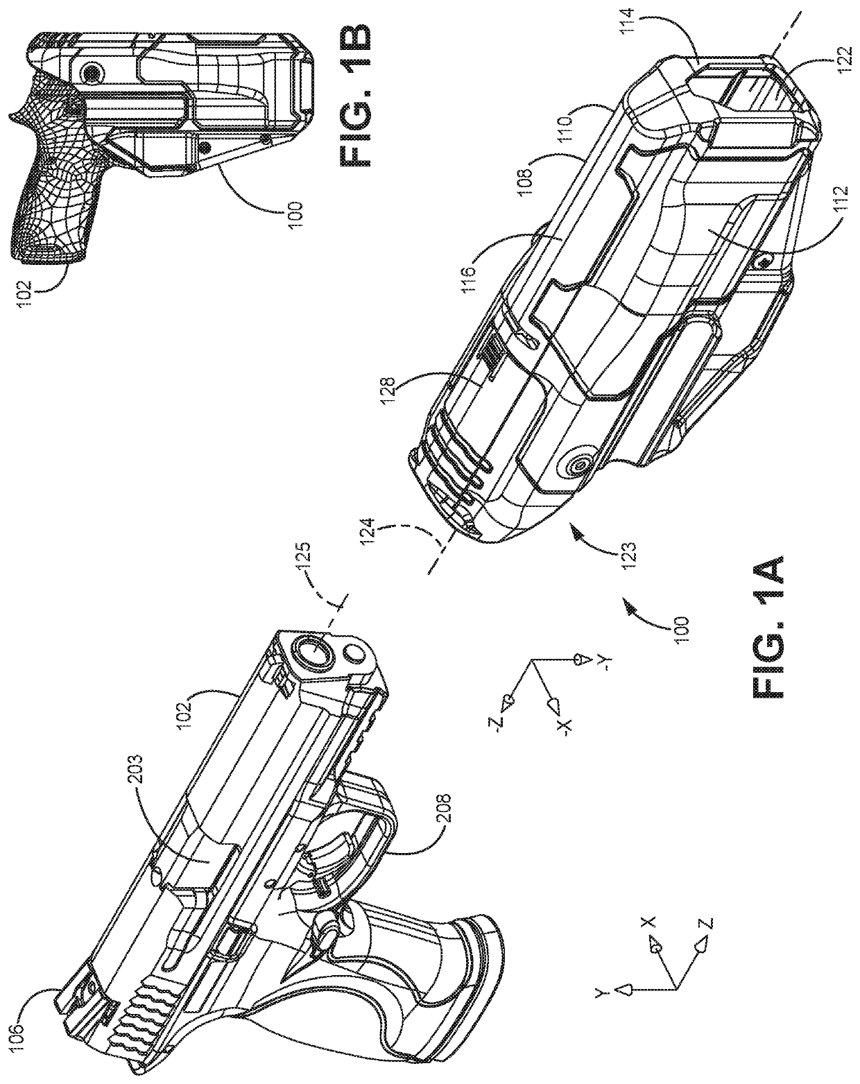
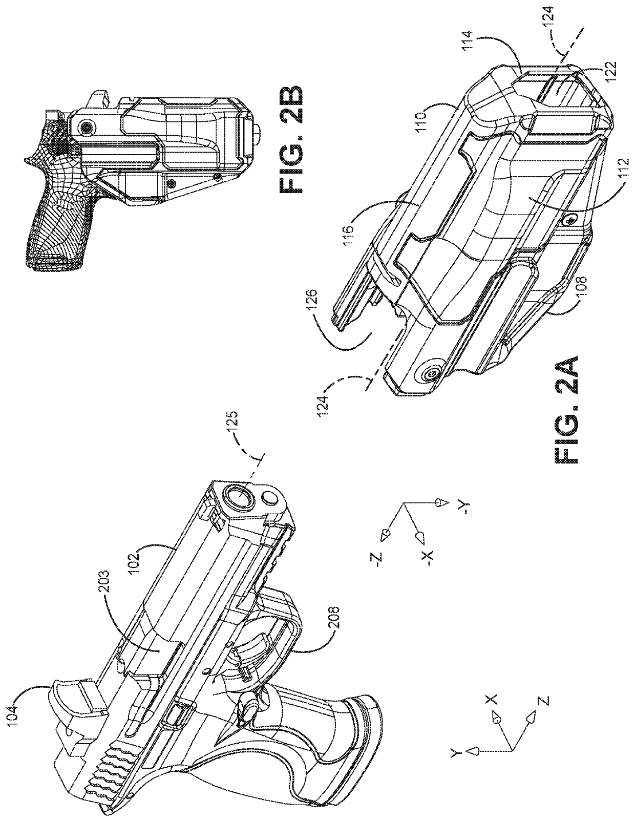
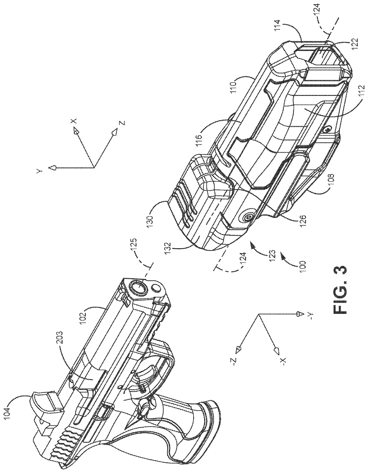
[0032]Referring to FIGS. 1A-3, a holster system 100 for receiving and releasably retaining a handgun 102 with or without a reflex sight 104 mounted thereto is disclosed. The holster 108 of the holster system 100 may comprise a holster body 110 comprising a distal side wall portion 112 disposed opposite a proximal side wall portion 114 and an upper wall portion 116 extending between the upper ends of the side wall portions. The wall portions of the holster body 110 may define a cavity 122 with an open rearward end 123. The cavity 122 having a handgun receiving and withdrawal axis 124 that is generally parallel to the handgun barrel axis 125. The holster body 110 defines a rear accessory sight opening 126 for receiving the handgun 102 with the reflex sight 104 attached thereto. With reference to the figures, the sight opening 126 may be positioned at a rearward end of the upper wall portion 116 and positioned intermediate the distal side wall portion 112 and the proximal side wall por...


PUM


Abstract

A holster system for receiving and releasably retaining a handgun with or without a reflex sight mounted thereon. The holster body comprises a pair of opposing side wall portions and an upper wall portion. The holster body may define a rear accessory sight opening for receiving the handgun with the reflex sight attached thereto. The holster system may include a first rear sight cover selectively and robustly coupleable to the holster body so as to cover the rear accessory sight opening when a handgun with conventional sights extending upwardly about ⅜ of an inch or less mounted thereto is used in conjunction with the holster system. The holster system may also include a second rear sight cover selectively coupleable to the holster body so as to cover the sight opening when a handgun with a reflex sight mounted thereto is used in conjunction with the holster system.

Description

CROSS-REFERENCE TO RELATED APPLICATIONS[0001]This application is a continuation of U.S. application Ser. No. 16 / 037,069, filed Jul. 17, 2018, which claims the benefit of U.S. Provisional Patent Application No. 62 / 533,281, filed Jul. 17, 2017, the disclosures of which are hereby incorporated by reference herein in their entirety.BACKGROUND OF THE DISCLOSURE[0002]Handguns that are carried by police and military are carried in holsters that are externally worn and that have varying degrees of security levels depending primarily upon on the intended context of use. Such holsters are formed of rigid polymers and cover most of the handgun frame, most or all of the slide portion, and usually all of the trigger guard of the handgun while leaving the hand grip exposed for grasping. The majority of such holsters for the police and military are worn adjacent to the left or right hip depending on whether the user is left or right handed and are worn with the handgun pointing downward when the u...

Claims


Application Information

Patent Timeline
Patent Type & Authority Patents(United States)
IPC IPC(8): F41C33/02F41C33/04F41G1/06
CPCF41C33/0209F41C33/0254F41C33/0263F41G1/06F41G1/16F41G1/30
Inventor SEREDAY, DANIEL D.HOUCK, LARRY A.
Owner VISTA OUTDOOR OPERATIONS
Learn More