
Jackladder flight member with replaceable or rotatable wear component

a technology of flight member and wear component, which is applied in the direction of conveyors, packaging, transportation and packaging, etc., can solve the problems of increasing the cost of what and increasing the overall wear life, and achieves the effects of quick and easy replacement, and rapid removal and replacemen

Active Publication Date: 2018-11-27
CRUCIBLE LLC
View PDF5 Cites 1 Cited by
  • Summary
  • Abstract
  • Description
  • Claims
  • Application Information

AI Technical Summary

Benefits of technology

This solution enables rapid and cost-effective replacement of worn wear plates, preserving the rest of the flight member and potentially using more wear-resistant materials, significantly reducing downtime and extending the overall life of the flight members, thus improving the efficiency and cost-effectiveness of the jackladder conveyer systems.

Problems solved by technology

This may increase overall wear life and decrease the cost of what it may have been to cast a flight member in a single alloy.

Method used


Image

  • Jackladder flight member with replaceable or rotatable wear component
  • Jackladder flight member with replaceable or rotatable wear component
  • Jackladder flight member with replaceable or rotatable wear component

Examples


Embodiment Construction

[0019]The foregoing and other features and advantages of the invention are apparent from the following detailed description of exemplary embodiments, read in conjunction with the accompanying drawings. The detailed description and drawings are merely illustrative of the invention rather than limiting, the scope of the invention being defined by the appended claims and equivalents thereof.

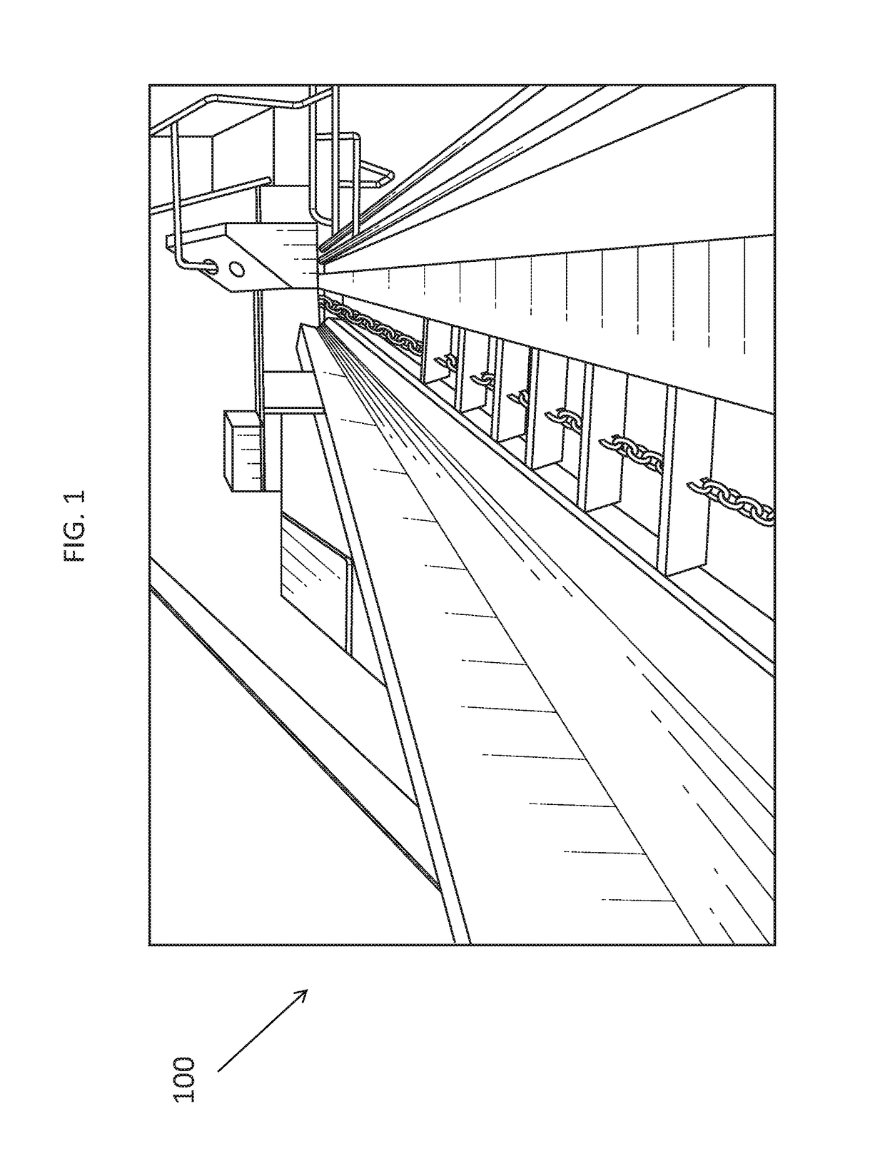
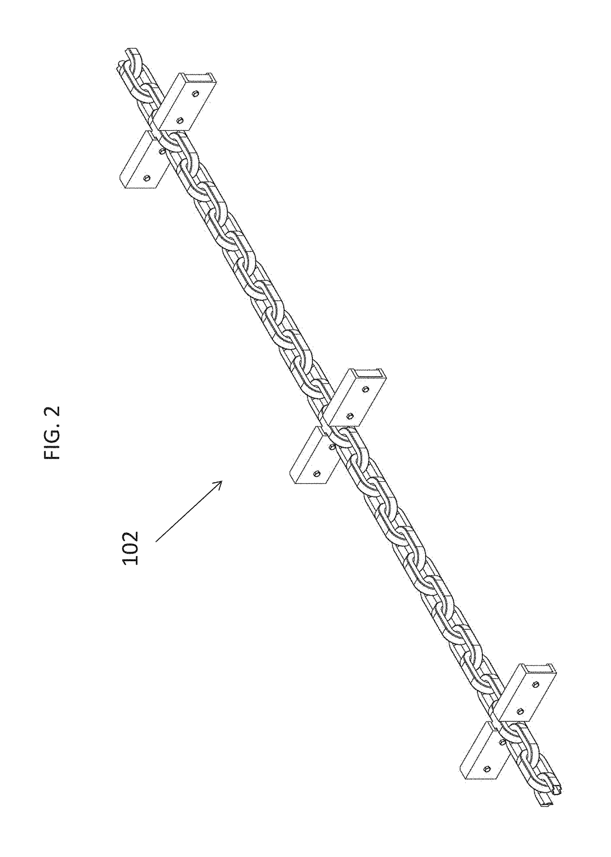
[0020]With specific reference to the drawings, FIG. 1 represents a jackladder conveyer system 100, comprising a loading trough, a ramp, a jackladder chain assembly 102, a second trough, and logs. The jackladder chain assembly 102 is further detailed in FIG. 2 which displays individual flight member assemblies interconnected by a chain.

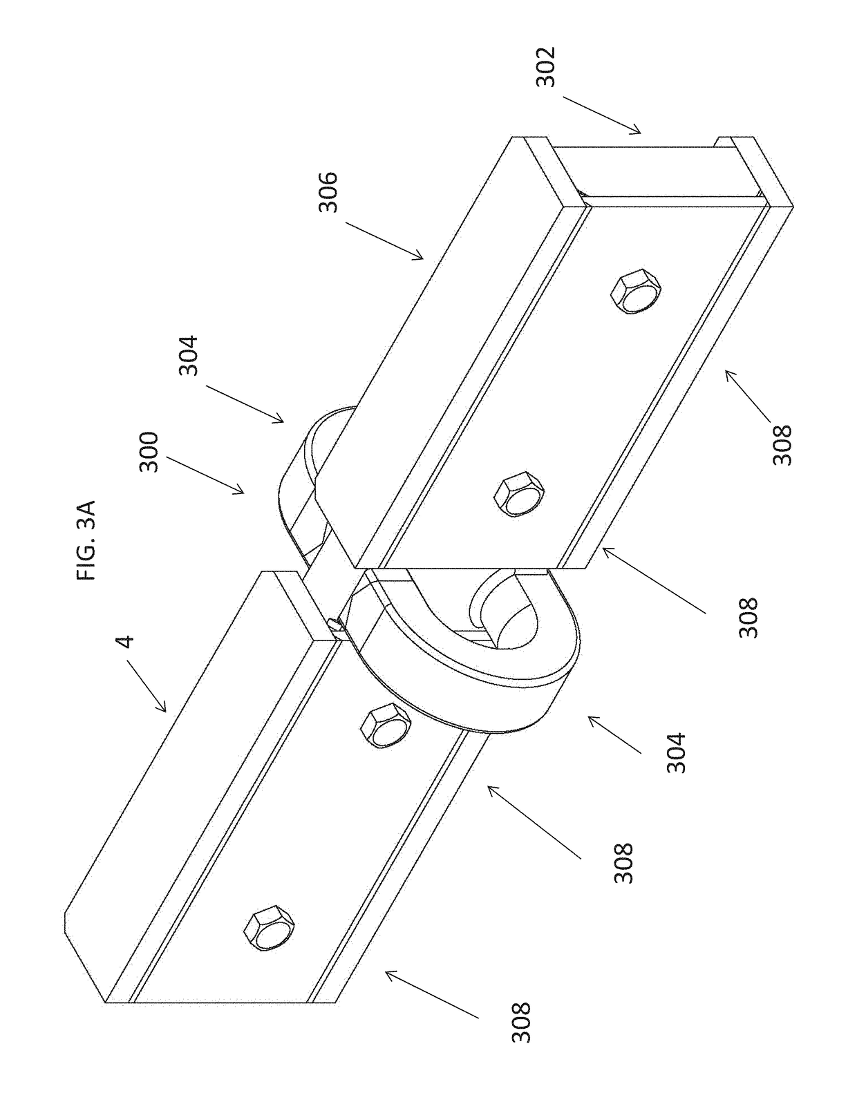
[0021]FIGS. 3A and 3B represent an embodiment of the flight member assembly 300. FIG. 3A an isometric view of the flight member assembly 300 comprising a base plate 302, chain link connector 304, wear plate components 306, wear plate coupling means 308. FIG. 3B is an i...


PUM


Abstract

The present invention is a jackladder flight member with replaceable or rotatable wear surfaces. Additional embodiments of the invention include a jackladder conveyer chain comprising flight members with replaceable and rotatable wear surfaces as well as a jackladder conveyer system comprising a jackladder chain comprising flight members with replaceable or rotatable wear surfaces and a method to replace or rotate or replace the replaceable or rotatable wear surfaces.

Description

BACKGROUND OF THE INVENTION[0001]The present invention pertains generally to the field of jackladder conveyer systems used in the logging industry. Jackladder conveyer systems are used to move logs into a chipper or sawmill. More particularly, this invention relates to the construction of the elements used within the jackladder system to move the logs up an incline known as “flights.” Flights are elongated members that are interconnected by a conveyer chain and run normal to the direction of the chain. As the conveyer chain traverses the incline of the system, the flights act to carry the logs up the incline and into a chipper or sawmill.[0002]As indicated in U.S. Pat. No. 5,441,092, a typical softwood log sawmill comprises saws installed on an upper deck, while ancillary equipment is installed at ground level. A sloping conveyor (the “jackladder”) brings up a continuous supply of logs from a log pond or storage yard to the upper deck where the saw is installed. The jackladder conve...

Claims


Application Information

Patent Timeline
Patent Type & Authority Patents(United States)
IPC IPC(8): B65G19/00B65G19/22B65G19/24B65G19/08
CPCB65G19/22B65G19/08B65G2207/48
Inventor ANDERSON, GARY W.COVIN, GRADY W.
Owner CRUCIBLE LLC
Learn More