Modular wind turbine rotor blade

a wind turbine and module technology, applied in the direction of wind motors, wind motors with parallel air flow, motors, etc., can solve the problems of large components, difficult to access, and long rotor blades, and achieve the effect of facilitating blade assembly and simple lamina

Active Publication Date: 2021-09-14
VESTAS WIND SYST AS
View PDF43 Cites 0 Cited by
  • Summary
  • Abstract
  • Description
  • Claims
  • Application Information

AI Technical Summary

Benefits of technology

[0009]Joining the modules together by means of a continuous spar structure results in a more simple and more robust joint than prior art joints described by way of the background. There is also no weight penalty with this method of joining the blade, whereas prior art joining methods generally require additional components to create and reinforce the joint.
[0041]The method may further comprise folding or coiling the free section of the or each spar structure before transporting the first blade module to the assembly site. This significantly reduces the space taken up by the first blade module in transit. The first and second blade modules may be transported together to the assembly site, for example on a suitable vehicle or inside a suitable container. Preferably the dimensions of the modules are such that the modules can fit inside a standard container. The length of the modules are conveniently shorter than the length of the blade when assembled. This allows longer blades to be transported than is currently possible by traditional means.

Problems solved by technology

The site may be remote and difficult to access, which makes transportation of large components, in particular the long rotor blades, problematic.
In use, rotor blades experience extremely high stresses, which can cause stress concentrations to form at the joints between the modules of modular rotor blades due to discontinuities in the structure at the joints.
These stress concentrations may result in damage to the modular rotor blades, for example cracks which require repairs and may reduce the lifespan of the modular rotor blades.
However, these joining methods tend to increase the weight of the rotor blades and add significant complexity to their design, manufacture and assembly.

Method used


Image

  • Modular wind turbine rotor blade
  • Modular wind turbine rotor blade
  • Modular wind turbine rotor blade

Examples


Embodiment Construction

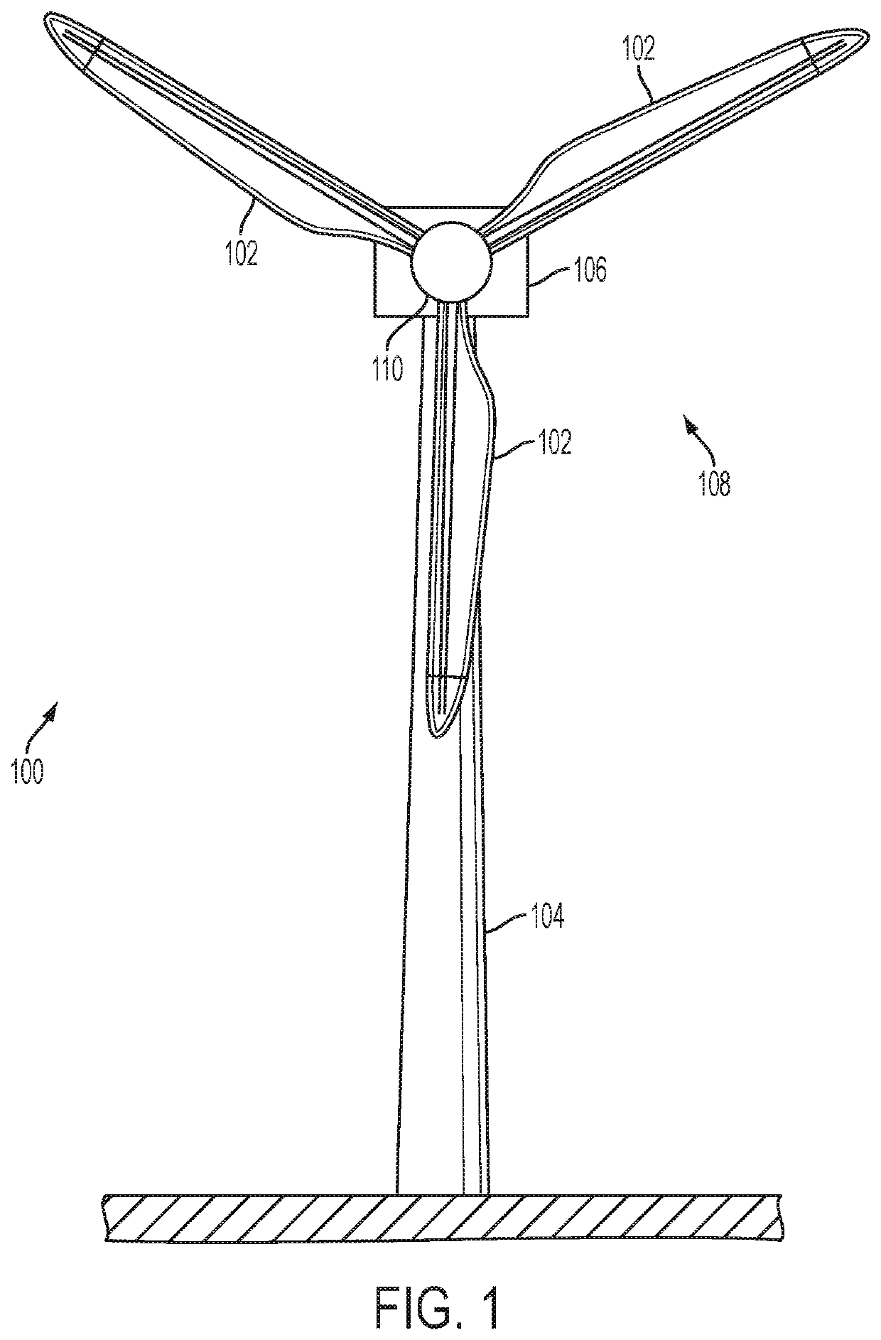
[0051]FIG. 1 shows a wind turbine 100 comprising three modular rotor blades 102 according to an embodiment of the invention. The wind turbine 100 comprises a tower 104 on which a nacelle 106 is supported. A rotor 108 is mounted to the front of the nacelle 106. The rotor 108 is operatively connected to a generator located inside the nacelle 106. The rotor 108 comprises a hub 110 on which the modular rotor blades 102 are mounted. The modular rotor blades 102 extend radially outward from the hub 110 and are equally spaced about a circular circumference of the hub 110.

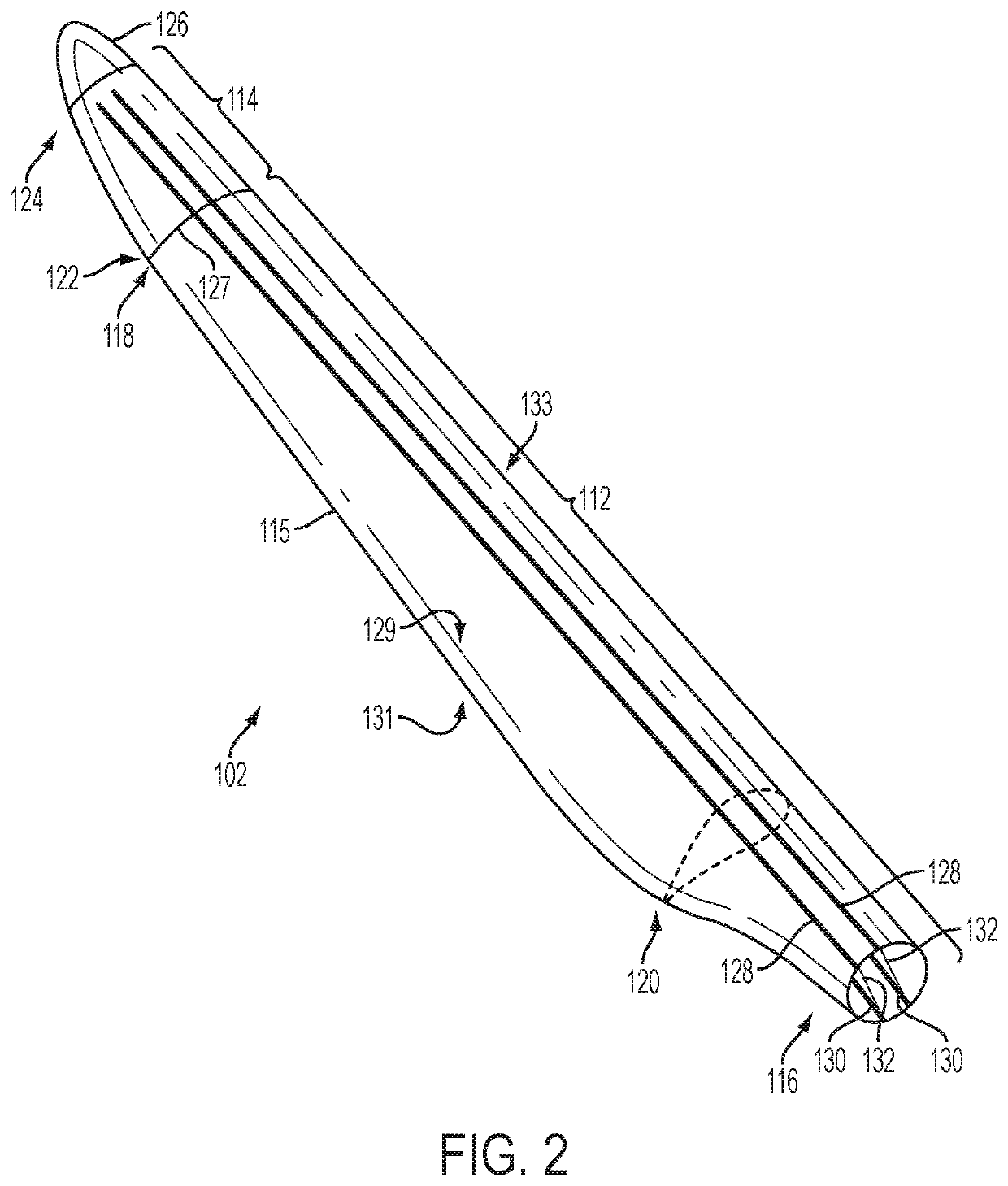
[0052]FIG. 2 shows a modular rotor blade 102 of the wind turbine 100 in more detail. The modular rotor blade 102 comprises an inboard blade module 112 and an outboard blade module 114. Each module 112, 114 comprises a substantially hollow outer shell 115 made primarily of glass-fibre reinforced plastic material.

[0053]The inboard module 112 extends in a longitudinal or spanwise direction between a root end 116 and an interf...


PUM


Abstract

A modular wind turbine blade is described. The blade has at least a first blade module and a second blade module connected to end to end. An interface is defined between the respective modules. The blade further comprises at least one longitudinally extending spar structure that forms part of the outer shells of the first and second blade modules when the modules are connected. The or each spar structure is substantially continuous and extends across the interface between the first and second blade modules when the modules are connected. The or each spar structure is integrated with the first blade module and the spar structure is folded or coiled to facilitate transportation of the module. The second blade module includes channels defined in the outer shell for receiving the or each spar structure when the modules are connected. In this way the spar structures also form part of the outer shell of the second module. A method of assembling the modular blade and a method of installing a wind turbine having a modular blade are also described.

Description

BACKGROUND[0001]The present invention relates generally to wind turbine rotor blades and in particular to a modular rotor blade for a wind turbine.[0002]Modern wind turbines are designed and manufactured to capture increasingly more energy from the wind to generate power. One way of increasing the energy capture of a wind turbine is to increase the swept area of the rotor blades, which means increasing the length of the rotor blades.[0003]In general, large wind turbines are assembled on site from components that are transported to the site. Typical components of a wind turbine include a plurality of rotor blades, a rotor hub, a nacelle and a tower. The site may be remote and difficult to access, which makes transportation of large components, in particular the long rotor blades, problematic. To resolve this problem, the rotor blades may be divided into two or more modules that are easier to transport, and which are connected together on site.[0004]In use, rotor blades experience ext...

Claims


Application Information

Patent Timeline
Patent Type & Authority Patents(United States)
IPC IPC(8): F03D1/06
CPCF03D1/0675F05B2240/302F05B2280/6003Y02E10/72
Inventor RANDALL, STEPHEN
Owner VESTAS WIND SYST AS
Why Eureka
Try Eureka