Electric propulsion system control apparatus
a control apparatus and electric propulsion technology, applied in process and machine control, instruments, navigation instruments, etc., can solve the problem of inaccurate detection of airspeed, achieve maximize propeller efficiency, and high degree of responsiveness
- Summary
- Abstract
- Description
- Claims
- Application Information
AI Technical Summary
Benefits of technology
Problems solved by technology
Method used
Image
Examples
first embodiment
[0056](First Embodiment)
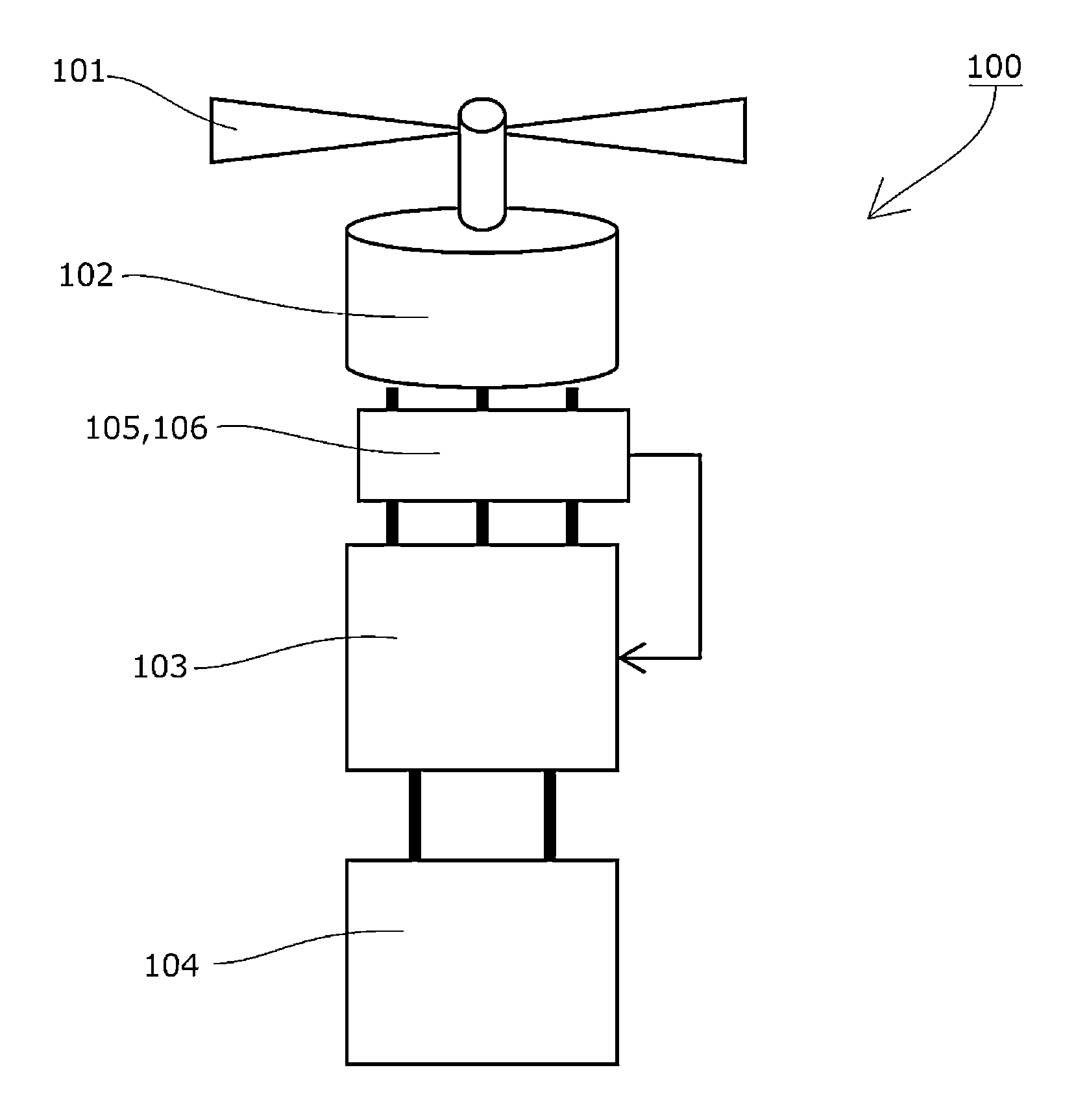
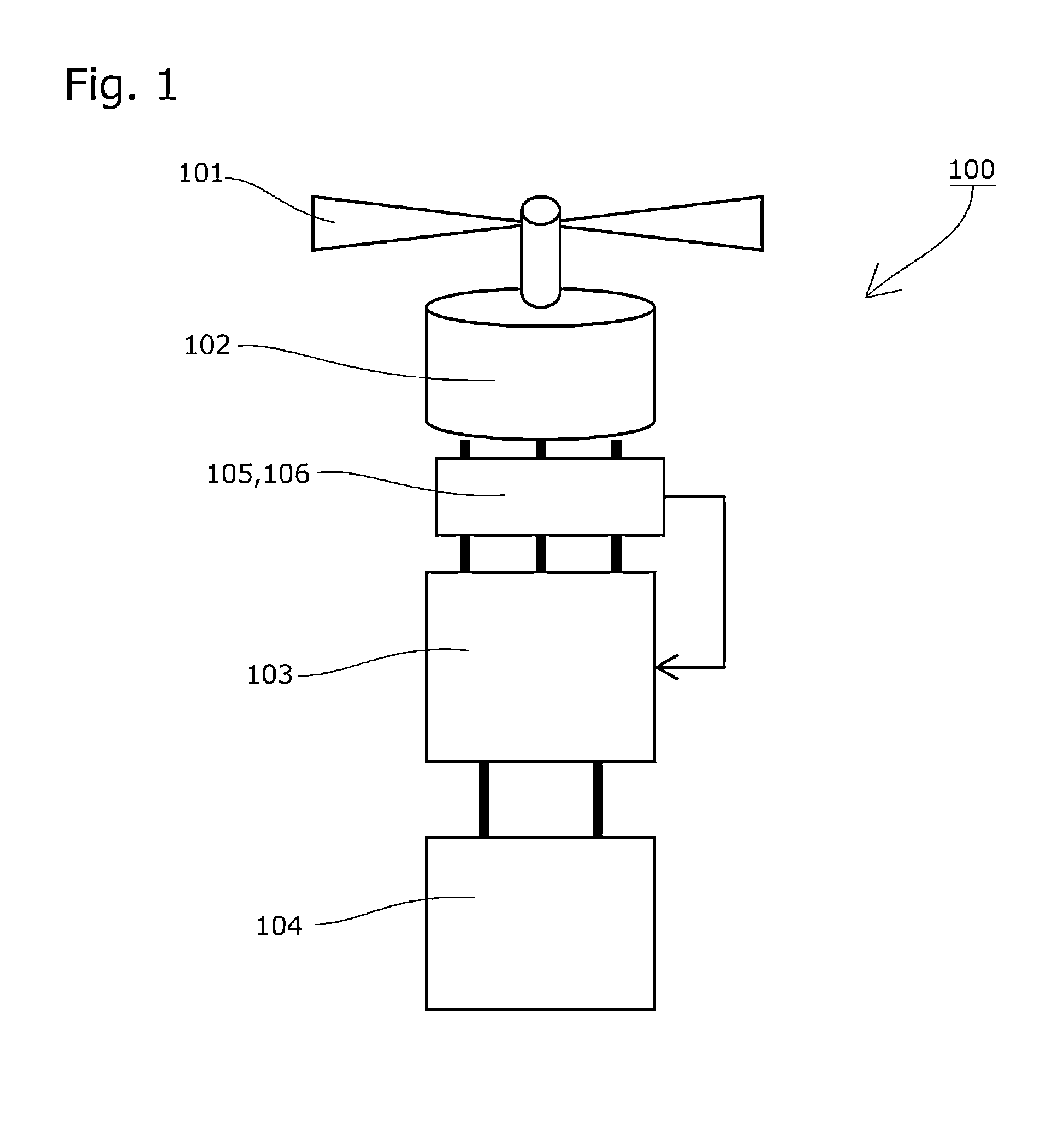
[0057]The electric propulsion system control apparatus 100 according to the present invention will now be described in further detail on the basis of FIG. 1.
[0058]The drive control means 103 includes a data set relating to the airspeed U, the torque τ and the rotation speed N of the propulsion propeller 101, and the atmospheric density ρ, such as those shown in FIGS. 4 and 5, and has a function for estimating the torque τ generated by the electric drive motor 102 from a current I supplied to the electric drive motor 102, which is obtained from the current detecting means 105, and a function (rotation speed detecting means) for estimating the rotation speed N from a voltage E applied to the electric drive motor 102, which is obtained from the voltage detecting means 106.
[0059]The drive control means 103 is capable of estimating the torque τ and the rotation speed N from the supplied current I and the applied voltage E obtained successively from the current det...
second embodiment
[0070][Second Embodiment]
[0071]An electric propulsion system control apparatus having a speed maintenance function, serving as another embodiment of the present invention, will now be described.
[0072]FIG. 8 shows a configuration in which a fixed pitch propeller 121 is employed as the propulsion propeller, and FIG. 9 shows a configuration in which a variable pitch propeller 131 is employed as the propulsion propeller.
[0073]The fixed pitch propeller 121 or the variable pitch propeller 131 is driven by the electric drive motor 102, which is controlled by the drive control means 103.
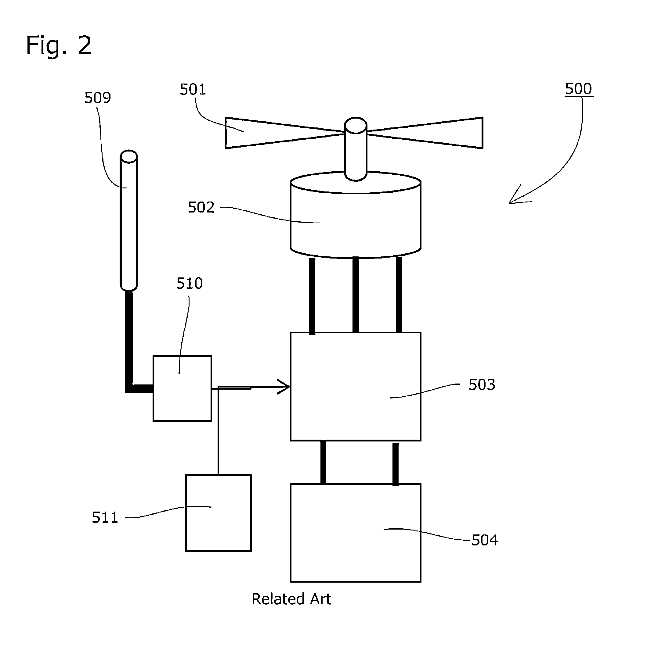
[0074]Further, for comparison, FIG. 10 shows a configuration employing airspeed detecting means constituted by the conventional Pitot tube 509, pressure pipe, pressure gauge 510, and so on, while FIG. 11 shows a configuration in which the propulsion propeller 501 is driven by an internal combustion engine 512, which is controlled by engine control means 513, using fuel supplied from a conventional fuel tank ...
third embodiment
[0084][Third Embodiment]
[0085]An electric propulsion system control apparatus having an efficiency maximization function, which serves as a further embodiment of the present invention, will now be described.
[0086]FIG. 15 shows a similar configuration to FIG. 9, i.e. a configuration in which the variable pitch propeller 131 is employed as the propulsion propeller.
[0087]The variable pitch propeller 131 is driven by the electric drive motor 102, which is controlled by the drive control means 103.
[0088]Further, for comparison, FIG. 16 shows a configuration employing airspeed detecting means constituted by the conventional Pitot tube 509, pressure pipe, pressure gauge 510, and so on.
[0089]FIG. 17 shows a propulsion system control sequence of the drive control means 103.
[0090]Assuming that an initial condition (U, ρ, P, N, β) of the propulsion system is (U0, ρ0, P0, N0, β0), the drive control means 103 detects U0, J0, CP0, ρ0 using the method described above.
[0091]Next, a value of J1 for ...
PUM
 Abstract
Description
Claims
Application Information
 - R&D
- Intellectual Property
- Life Sciences
- Materials
- Tech Scout
- Unparalleled Data Quality
- Higher Quality Content
- 60% Fewer Hallucinations
Browse by: Latest US Patents, China's latest patents, Technical Efficacy Thesaurus, Application Domain, Technology Topic, Popular Technical Reports.
© 2025 PatSnap. All rights reserved.Legal|Privacy policy|Modern Slavery Act Transparency Statement|Sitemap|About US| Contact US: help@patsnap.com


