
Multi-input voltage converter

a voltage converter and input voltage technology, applied in the field of voltage converters, can solve the problems of difficult circuit volume reduction and large size of the architecture, and achieve the effect of reducing circuit size and cost, and simplifying circuit architectur

Active Publication Date: 2021-09-14
PEGATRON
View PDF22 Cites 0 Cited by
  • Summary
  • Abstract
  • Description
  • Claims
  • Application Information

AI Technical Summary

Benefits of technology

The present invention combines the features of two types of converters to create a single output structure that works with multiple input voltages. This simplifies the circuit design, reduces its size and cost.

Problems solved by technology

Another way is to have each of input voltages have its own voltage convertor, but this may cause the circuit architecture to be very large in size and make it difficult for the circuit volume to be reduced.
Therefore, it is an important issue in the industry to provide a multi-input voltage converter with a simple circuit structure and different conversion efficiencies of input voltages at respective optimum efficiency points.

Method used


Image

  • Multi-input voltage converter
  • Multi-input voltage converter
  • Multi-input voltage converter

Examples


first embodiment

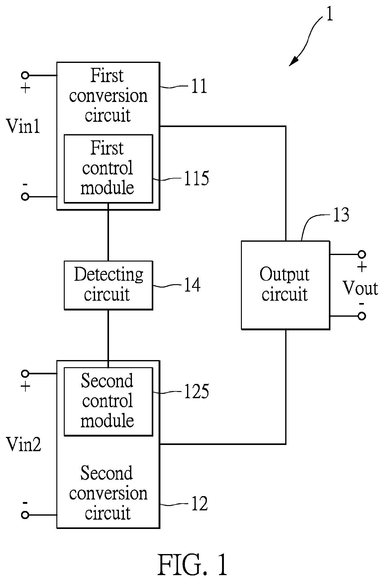
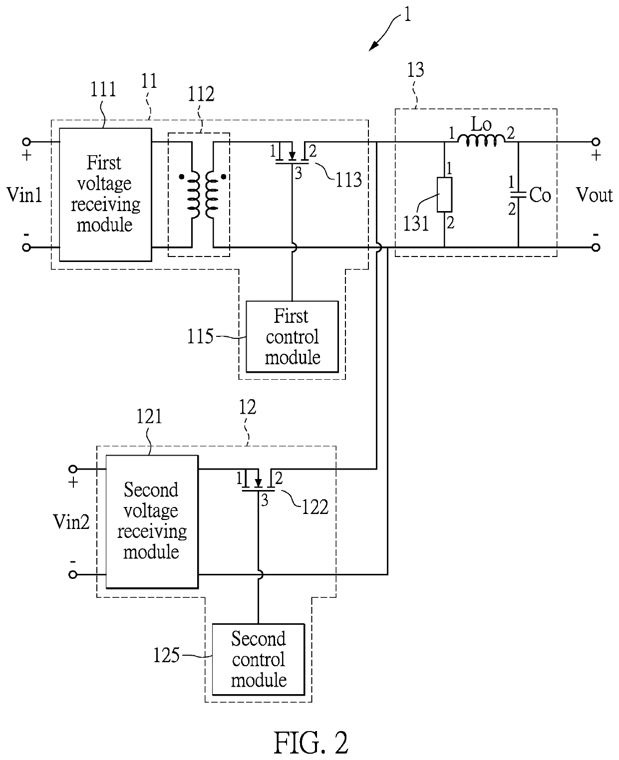
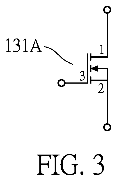
[0017]Referring to FIG. 1, FIG. 2, and FIG. 3, FIG. 1 is a schematic diagram of a multiple input voltage converter in accordance with an embodiment of the present disclosure. FIG. 2 is a schematic diagram of a multiple input voltage converter in accordance with an embodiment of the present disclosure. FIG. 3 is a schematic illustration of the conduction element of FIG. 2.

[0018]In the present embodiment, the multi-input voltage converter 1 includes a first conversion circuit 11, a second conversion circuit 12, an output circuit 13, and a detection circuit 14.

[0019]The first conversion circuit 11 is electrically connected to the output circuit 13 and the detection circuit 14. Similarly, the second conversion circuit 12 is electrically connected to the output circuit 13 and the detection circuit 14.

[0020]The first conversion circuit 11 receives a first input voltage Vin1 and converts the first input voltage Vin1 as an output voltage Vout. The second conversion circuit 12 receives a sec...

second embodiment

[0042]Referring to FIG. 4, FIG. 4 is a schematic diagram of another multiple input voltage converter in accordance with an embodiment of the present disclosure. In the embodiment, the multi-input voltage converter 1′ differs from the multi-input voltage converter 1 of the previously described embodiment in that the first conversion circuit 11 of the multi-input voltage converter 1 includes a first switch 113, and the first conversion circuit 11 of the multi-input voltage converter 1′ in the embodiment includes a fourth diode element 113′. Furthermore, the output circuit 13 of the multi-input voltage converter 1 includes a conduction element 131, and the conduction element 131 is a switch. In the embodiment, the output circuit 13 includes a sixth diode 131′. Other circuit architectures, operations, and related components are generally similar to those of the first embodiment, and therefore are not described here.

[0043]In the embodiment, the first terminal of the fourth diode element ...


PUM


Abstract

A multi-input voltage converter includes an output circuit, a first conversion circuit, and a second conversion circuit. The first conversion circuit includes a first voltage receiving module, a first transformer, a first switch. The second conversion circuit includes a second voltage receiving module, a second switch. When the second voltage receiving module receives the second input voltage, the second switch is turned on to operate, and the output circuit outputs the output voltage.

Description

CROSS-REFERENCE TO RELATED PATENT APPLICATION[0001]This application claims the benefit of priority to Taiwan Patent Application No. 107133822, filed on Sep. 26, 2018. The entire content of the above identified application is incorporated herein by reference.[0002]Some references, which may include patents, patent applications and various publications, may be cited and discussed in the description of this disclosure. The citation and / or discussion of such references is provided merely to clarify the description of the present disclosure and is not an admission that any such reference is “prior art” to the disclosure described herein. All references cited and discussed in this specification are incorporated herein by reference in their entireties and to the same extent as if each reference was individually incorporated by reference.FIELD OF THE DISCLOSURE[0003]The present disclosure relates to a voltage converter, and more particularly to a voltage converter with multiple input voltag...

Claims


Application Information

Patent Timeline
Patent Type & Authority Patents(United States)
IPC IPC(8): H02J1/10H02M3/156H02M3/335H02M1/00
CPCH02J1/102H02M1/0083H02M3/156H02M3/33538H02M3/33523H02M3/158H02M3/33546H02M3/33553H02M3/33592H02M3/3372H02M1/10H02M1/08H02M1/008
Inventor CHEN, HAO-MING
Owner PEGATRON
Learn More