
Cable tray firestop device

a firestop device and cable tray technology, applied in the direction of fireproofing, mechanical equipment, pipes, etc., can solve the problems of time-consuming installation and compromised opening of conventional systems

Active Publication Date: 2021-09-21
SPECIFIED TECH
View PDF28 Cites 0 Cited by
  • Summary
  • Abstract
  • Description
  • Claims
  • Application Information

AI Technical Summary

Problems solved by technology

As with other cable passages, the cable tray creates an opening through the barriers which raises a potential hazard in that a fire can use those opening to pass through the construction barrier, which of itself is an effective fire barrier, and the fire can then spread to adjoining areas of the building.
The problem with conventional systems is the removal and non-replacement of materials, leaving the opening compromised.
Additionally, such conventional systems can be time consuming to install.

Method used


Image

  • Cable tray firestop device
  • Cable tray firestop device
  • Cable tray firestop device

Examples


Embodiment Construction

[0023]In the drawings, like numerals indicate like elements throughout. Certain terminology is used herein for convenience only and is not to be taken as a limitation on the present invention. The following describes preferred embodiments of the present invention. However, it should be understood, based on this disclosure, that the invention is not limited by the preferred embodiments described herein.

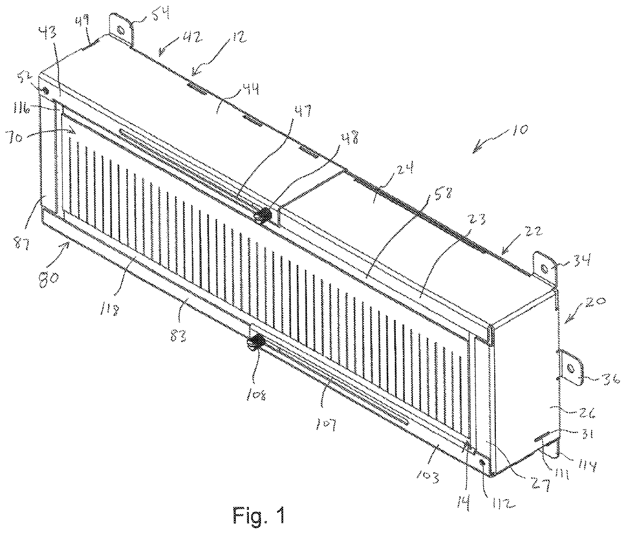
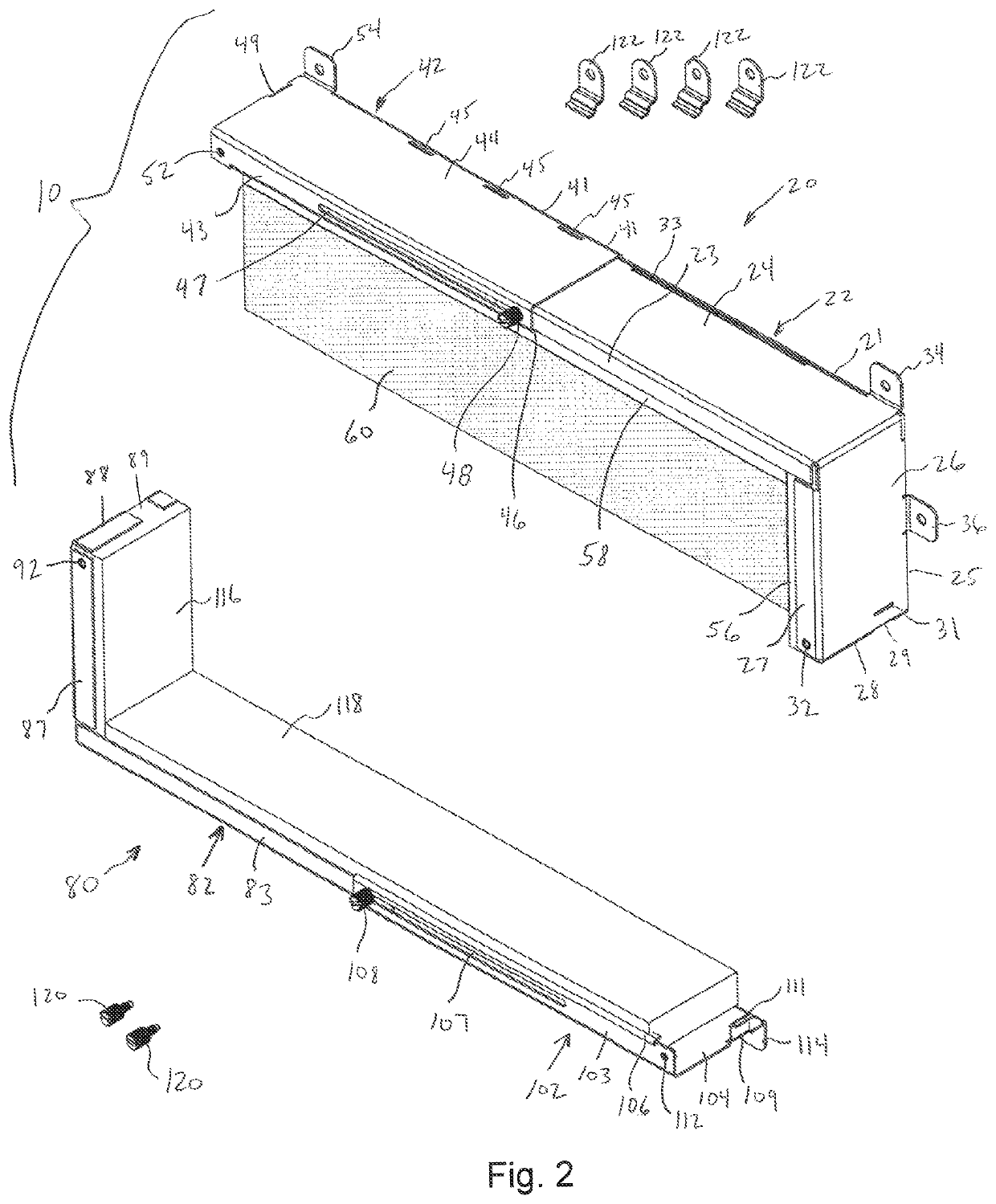
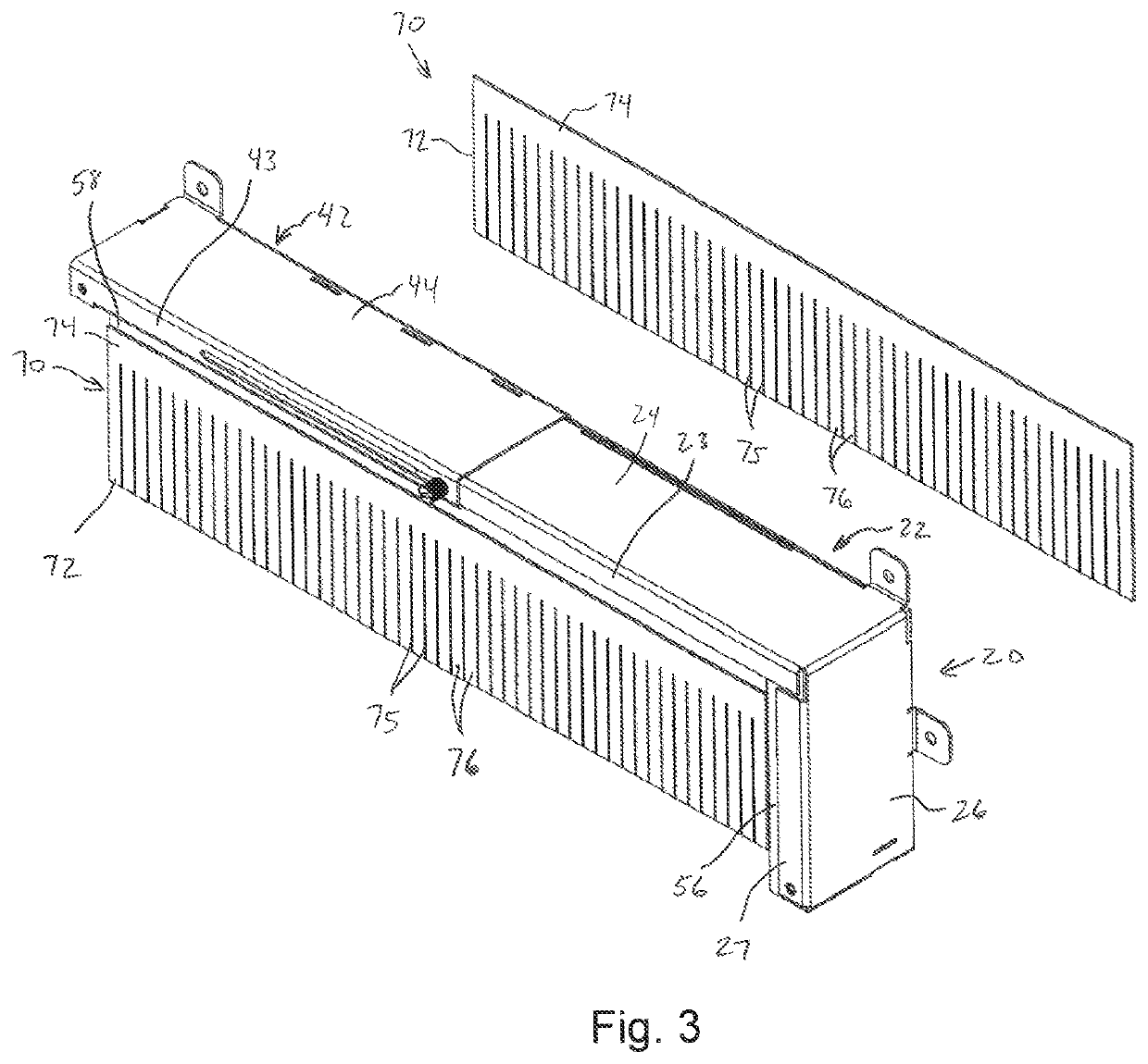
[0024]Referring to FIGS. 1-8, a firestopping apparatus 10 in accordance with an exemplary embodiment of the invention will be described. The firestopping apparatus 10 generally comprises first and second housing members 20, 80 that are interconnected to one another to define a housing 12 defining a through passage 14. The housing 12 generally has a rectangular configuration which complements the shape of the cable tray about which the firestopping apparatus 10 is positioned. While the illustrated housing 12 is adjustable in the lengthwise direction to accommodate trays of different wid...


PUM


Abstract

A firestopping apparatus including a housing defined by first and second housing members. Each housing member includes a width direction wall panel and a height direction wall panel. The width direction wall panel of the first housing member is configured to connect with the height direction wall panel of the second housing member and the width direction wall panel of the second housing member is configured to connect with the height direction wall panel of the first housing member to define an assembled housing with a through passage. Intumescent material is positioned along an inner surface of each wall panel. A compressible foam is positioned within the intumescent material and substantially closes off the through passage.

Description

[0001]This application claims the benefit of U.S. Provisional Application No. 62 / 771,225, filed Nov. 26, 2018, the contents of which are incorporated herein by reference.FIELD OF THE INVENTION[0002]The invention generally relates to apparatus for providing a firestop within a construction opening and, more particularly, to a firestopping apparatus configured to be positioned about a cable tray and having intumescent pads that form a confinement area about penetrating members passing through the construction opening.BACKGROUND OF THE INVENTION[0003]It is commonplace in the construction and renovation of commercial and residential buildings for the need to pass cables, conduits and the like through construction barriers such as walls, floors and ceilings. In some instances, the cables are supported on a cable tray which extends through the construction barrier. The cable tray 204 is typically an elongate support structure having a support surface 206 with a pair of side walls 208 to d...

Claims


Application Information

Patent Timeline
Patent Type & Authority Patents(United States)
IPC IPC(8): F16L5/04H02G3/22E04B1/94H02G3/04F16L3/26
CPCE04B1/947H02G3/0412H02G3/0418H02G3/22F16L3/26F16L5/04H02G3/0437E04B5/48A62C2/065
Inventor STAHL, JR., JAMES P.GANDOLFO, PAULJANUS, NEALFAIELLO, STEVENLOPES, JULIO
Owner SPECIFIED TECH
Learn More