Torque limiter

a limiter and torque technology, applied in the direction of couplings, wound springs, slipcouplings, etc., can solve the problems of difficult to increase durability, and achieve the effect of simplifying the supporting structure and effectively preventing or reducing

Active Publication Date: 2021-09-28
SANCALL CORP
View PDF5 Cites 0 Cited by
  • Summary
  • Abstract
  • Description
  • Claims
  • Application Information

AI Technical Summary

Benefits of technology

[0017]Since the torque limiter according to the present invention includes the first rotator having the first end surface and the first outer circumferential surface, the second rotator having the second end surface and the second outer circumferential surface and the coil spring, wherein the first and second rotators are disposed coaxially with each other with the first contact region on the first end surface is in contact with the second contact region on the second end surface, the coil spring is inserted around the first and second rotators so as to bridge the first and second outer circumferential surfaces, and the difference is provided between the maximum static frictional force between the coil spring and the first outer circumferential surface and the maximum static frictional force between the coil spring and the second outer circumferential surface such that, when rotational torque that is in the direction of increasing the diameter of the coil spring and that is less than a predetermined value is applied to the first or second rotator, the first and second rotators integrally rotate via the coil spring, and one of the first and second rotators relatively rotates relative to the other of the first and second rotators together with the coil spring when the rotational torque is greater the predetermined value, it is possible to prevent the rotational torque from being locally applied to the coil spring to increase durability.
[0019]The preferable configuration makes it possible to effectively prevent or reduce the possibility of the occurrence of the coil spring entering a gap that may appear between the first and second end surfaces and simplify a supporting structure for supporting the first and second rotators.

Problems solved by technology

Meanwhile, in the above conventional torque limiter, force that acts on the outer race is locally applied to the engagement part of the coil spring, and thus there is the problem in that it is difficult to increase durability.

Method used


Image

  • Torque limiter
  • Torque limiter
  • Torque limiter

Examples


Embodiment Construction

[0040]Below, a preferable embodiment of the torque limiter according to the present invention will now be described with reference to the appended drawings.

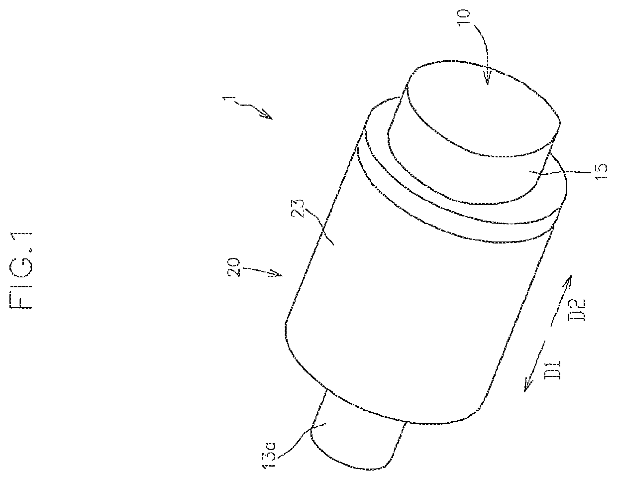
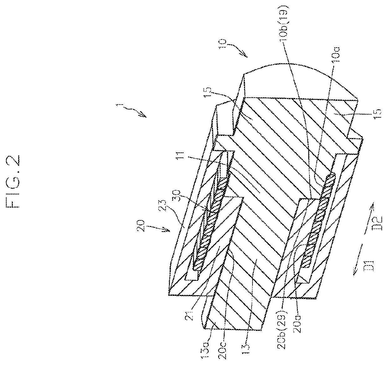
[0041]FIGS. 1 to 3 respectively show a perspective view, a perspective cross-sectional view, and an exploded perspective cross-sectional view of a torque limiter 1 according to the present embodiment.

[0042]As shown in FIGS. 1 to 3, the torque limiter 1 includes a first rotator 10 and a second rotator 20 coaxially disposed so as to be relatively rotatable, and a coil spring 30 externally fitted so as to bridge a first outer circumferential surface 10a of the first rotator 10 and a second outer circumferential surface 20a of the second rotator 20.

[0043]The first rotator 10 has a first end surface 10b facing in a first axial direction D1 and the first outer circumferential surface 10a which extends from the radially outer edge of the first end surface 10b in a second axial direction D2 opposite to the first axial direction D1 and to...


PUM


Abstract

In a torque limiter of the present invention, a difference is provided between a maximum static frictional force between the coil spring and the first outer circumferential surface and a maximum static frictional force between the coil spring and the second outer circumferential surface such that, when rotational torque in a direction of increasing the diameter of the coil spring and less than a predetermined value is applied to the first or second rotator, the first and second rotators integrally rotate via the coil spring, and one of the first and second rotators relatively rotates relative to the other of the first and second rotators together with the coil spring when the rotational torque is greater the predetermined value.

Description

FIELD OF THE INVENTION[0001]The present invention relates to a torque limiter utilized as a separation roller in a sheet feeding mechanism or the like.BACKGROUND ART[0002]A torque limiter that includes an inner race, a coil spring wound around the inner race, and a hollow outer race accommodating the inner race around which the coil spring is wound, and that is configured such that when external force (rotational torque) applied to the outer race is less than or equal to a predetermined threshold value, relative rotation of the outer race around the axis relative to the inner race is prohibited, and when the external force exceeds the threshold value, relative rotation of the outer race around the axis relative to the inner race is permitted, is widely used as, for example, a separation roller in a sheet feeding mechanism for feeding sheets of paper or the like one by one (see, for example, Patent Literature 1 below).[0003]The coil spring has a main body wound around the inner race ...

Claims


Application Information

Patent Timeline
Patent Type & Authority Patents(United States)
IPC IPC(8): F16D3/02F16D7/02F16D43/21F16F1/06
CPCF16D7/022F16D3/02F16D43/211F16F1/06F16F15/123F16F2222/04
Inventor KUMAGAI, RYOUKEI
Owner SANCALL CORP
Why Eureka
Try Eureka