
Spark plug testing kit

a technology of spark plugs and testing kits, which is applied in the manufacture of spark plugs, spark plugs, instruments, etc., can solve the problems of operator electrocution, fuel may be inadvertently ignited, and d1 suffers from several, so as to prevent inadvertent shock to the user

Active Publication Date: 2018-10-30
LEESON JOHN +2
View PDF16 Cites 0 Cited by
  • Summary
  • Abstract
  • Description
  • Claims
  • Application Information

AI Technical Summary

Benefits of technology

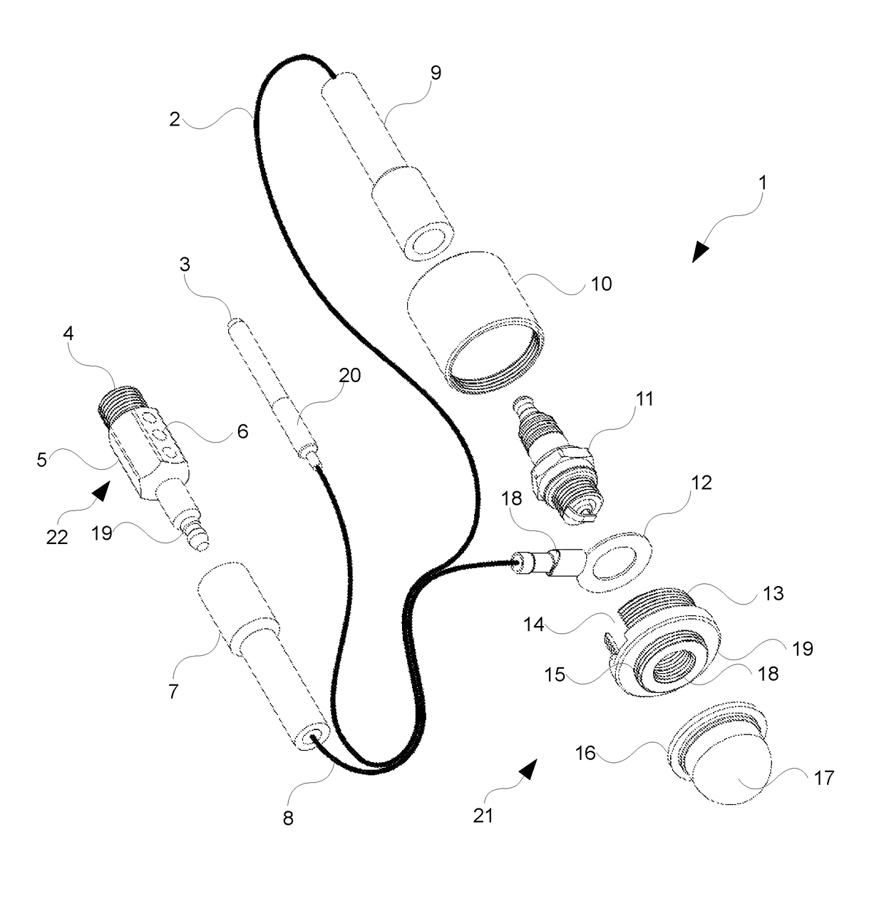
[0031]As such, with the foregoing in mind, in accordance with an embodiment, there is disclosed a spark plug testing kit comprising: a spark observation device; a spark plug opening engaging device; and an earth lead electrically connecting the spark observation device and the spark plug opening engaging device wherein: the spark observation device comprises a transparent observation chamber so as to allow for the viewing of the spark gap of a spark plug installed therein in use, and wherein the observation chamber may be substantially airtight so as to substantially prevent or reduce the possibility of the inadvertent ignition of fuel; and the spark plug opening engaging device: is configured for engaging a spark plug opening of the spark plug once the spark plug has been removed for observation so as to: substantially prevent debris from falling in through the opening; and serve as an engine block electrical connection contact for the earth lead; and comprises at least one exhaust for chamber decompression.

Problems solved by technology

Such an approach is dangerous in that fuel may be inadvertently ignited, the operator electrocuted and / or debris falling into the combustion chamber via the spark plug opening.
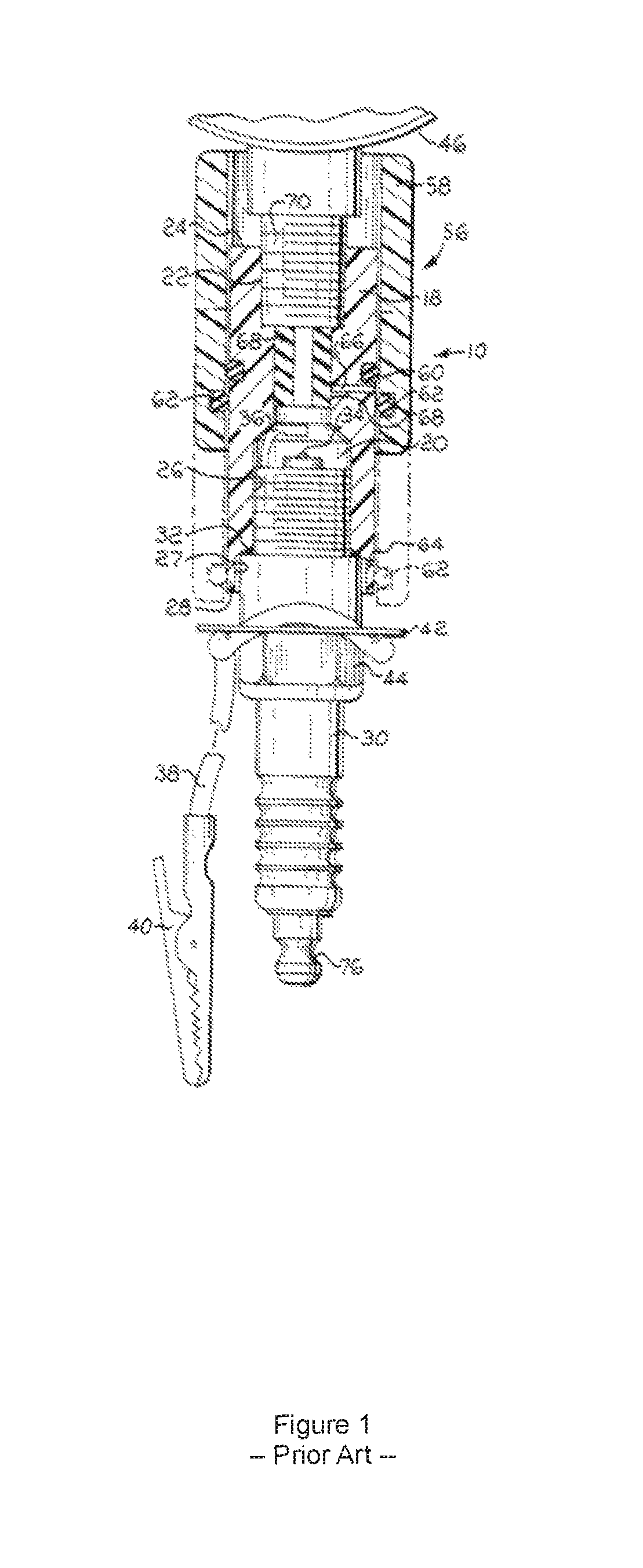
However, D1 suffers from several disadvantages including safety.
For example, the removal of the spark plug allows potentially engine damaging debris from falling into the cylinder chamber.
Furthermore, the utilisation of the crocodile clip 14 connected to any suitable ground point on the engine is not reliable in that it does not always form a reliable electrical connection thereby potentially affecting the spark and is furthermore inconvenient to use in having to find and locate a suitable attachment point.
Furthermore, the electrical leads of D1 are exposed which may inadvertently result in the 19 kV electrocution of the operator.
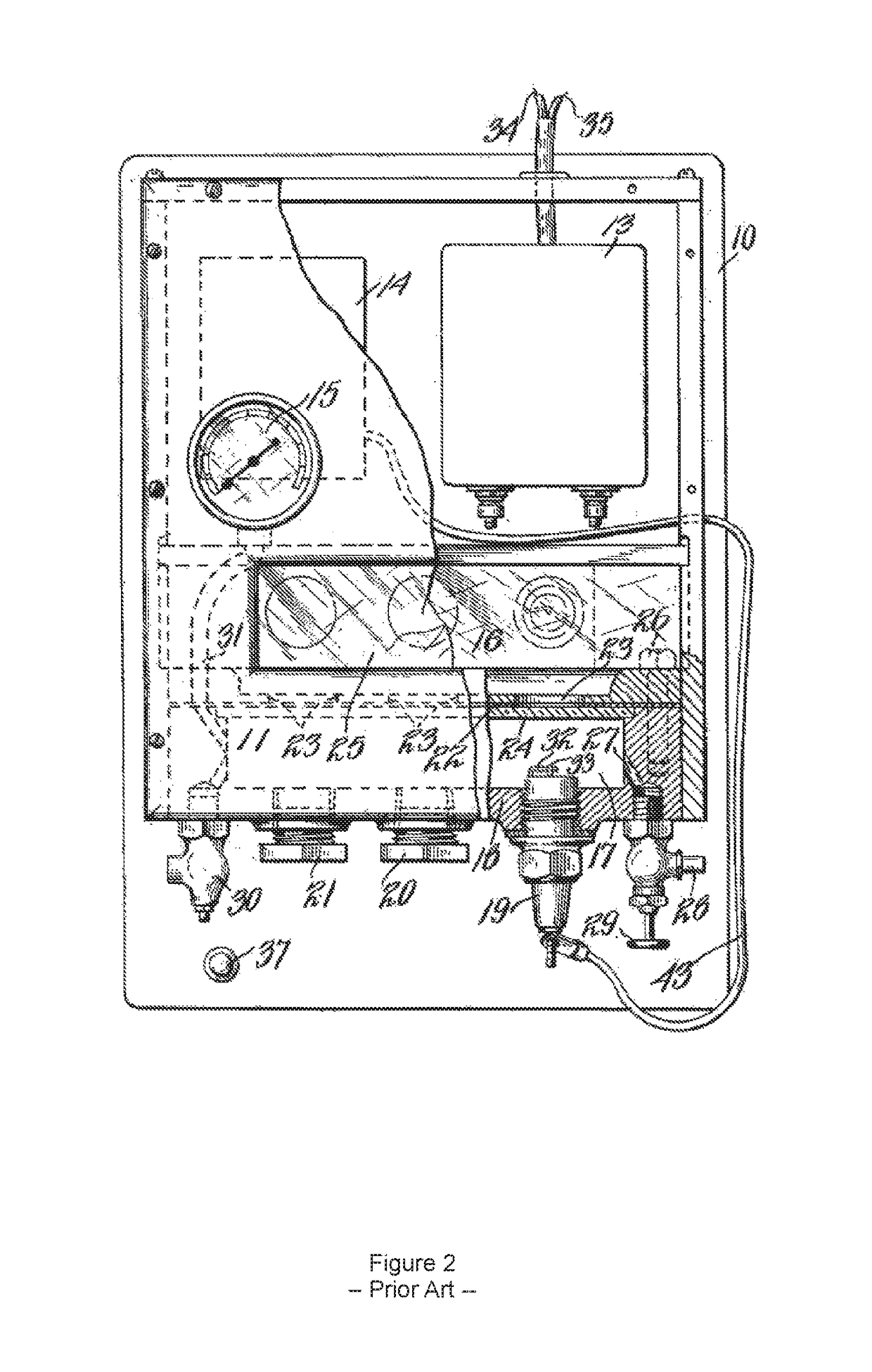
Furthermore, D2, in incorporating inbuilt electrical componentry, is incapable of testing the electrical distribution system / magneto and the like of the actual engine while simultaneously testing the spark plug.
However, D3 is not dissimilar from D2 in the construction and arrangement thereof being suited for a laboratory environment, or and including in the incorporation of inbuilt electrical componentry and the like and is therefore not suited for testing of a spark plug in conjunction with the electrical distribution system of the actual engine itself as can the spark plug testing kit of the present embodiments disclosed herein.
However, the crocodile clip 40 of D1 does not provide a reliable electrical connection.
Furthermore, the testing kit of D1 may allow debris to inadvertently enter the combustion chamber during testing and therefore damage the engine.
However, D4 is directed to compression testing, not electrical testing of an engine and a skilled person could not be have reasonably been expected to combine the disclosures of D1 and D4 together given these differing and distinct skill sets.
Furthermore, it could not be reasonably be expected for the skilled person to have sought to blocked or otherwise engaged the spark plug opening because the problem of debris falling into the chamber is not even recognised by the prior art on record (as is evidenced by the discloses of D1-D4).
Furthermore, even assuming that the person skilled had arrived at the utilisation of a spark plug opening engaging device, it could not have been reasonably expected for such spark plug opening engaging device to have an exhaust to allow for the decompression of the chamber to ease cranking cranking.

Method used


Image

  • Spark plug testing kit
  • Spark plug testing kit
  • Spark plug testing kit

Examples


Embodiment Construction

[0052]For the purposes of promoting an understanding of the principles in accordance with the disclosure, reference will now be made to the embodiments illustrated in the drawings and specific language will be used to describe the same. It will nevertheless be understood that no limitation of the scope of the disclosure is thereby intended. Any alterations and further modifications of the inventive features illustrated herein, and any additional applications of the principles of the disclosure as illustrated herein, which would normally occur to one skilled in the relevant art and having possession of this disclosure, are to be considered within the scope of the disclosure.

[0053]Before the structures, systems and associated methods relating to the spark plug testing kit are disclosed and described, it is to be understood that this disclosure is not limited to the particular configurations, process steps, and materials disclosed herein as such may vary somewhat. It is also to be unde...


PUM


Abstract

There is provided a spark plug testing kit for safe and convenient testing of petrol engines. The testing kit has a spark observation device within which a spark gap of a spark plug installed therein may be observed in use. The kit has a positive lead for connection to the engine distributor and an earth lead configured for connection to a spark plug opening engaging device. The spark plug engaging opening device comprises threading for turning into a spark plug socket of an engine block and defines an elongate male electrical connection nut standing proud therefrom over which a corresponding electrical connection of the earth lead may be easily and safely electrically connected. The spark plug engaging opening device further comprises exhaust ports through a side of the device for engine decompression during cranking.

Description

FIELD OF THE INVENTION[0001]The present invention relates to a spark plug testing kit and in particular, but not necessarily entirely, to a spark plug testing kit that allows for the testing of a spark plug in a manner that substantially reduces the possibility of inadvertent ignition or explosion of fuel.BACKGROUND AND SUMMARY OF THE INVENTION[0002]In the embodiments provided herein, there is disclosed a portable, simple, safe and reliable spark plug testing kit for utilisation on small petrol engines. For example, the spark plug testing kit may be stored on a toolbox or the like and utilised where and when necessary such as, for example, problem solving a recalcitrant lawnmower.[0003]The conventional problem-solving approach for small petrol engines is to remove the spark plug and place the spark plug on the engine block to form a ground connection whereafter the engine is cranked to view the spark within the spark gap of the spark plug. Such an approach is dangerous in that fuel ...

Claims


Application Information

Patent Timeline
Patent Type & Authority Patents(United States)
IPC IPC(8): F02P17/12H01T13/58H01T21/02G01R31/00
CPCF02P17/12H01T21/02H01T13/58G01R31/00F02P13/00
Inventor LEESON, JOHN
Owner LEESON JOHN
Learn More