Method of optimization of cutting of flat products made of natural material, mainly of wood, and system for its realization

a technology of natural material and flat product, applied in the direction of computer control, program control, instruments, etc., can solve the problem that the single side scanning cannot be assessed, and achieve the effect of reducing environmental burden, increasing economic yield of available natural material, and flexible method and system

Active Publication Date: 2021-10-12
BIATEC GRP AS
View PDF19 Cites 0 Cited by
  • Summary
  • Abstract
  • Description
  • Claims
  • Application Information

AI Technical Summary

Benefits of technology

[0010]In the grown natural materials such as wood there is often a relation between the defects on one side and on the opposite side of the plank. Gathering of two scans from a single plank simplifies the subsequent recognition and classification of the defects. More complex information about the material is gathered in such a way that the material is optically scanned on all surfaces—that is, from sides, too.
[0013]The use of the computer tomography during the optical scanning allows connecting the results of these two methods during the classification of the defects. Internal non-homogeneity of the material detected by the computer tomography allows analyzing more reliably that a defect detected on the outer surface by the optical scan at the given place of the plank has a peculiar character specific for the given type of the defect. The use of the optical scanning and computer tomography for a single plank brings about synergic effect; the reliability of classification of defects increases, the number of waste products diminishes.
[0018]During the optimalization of cutting by means of a scanning and recognition of the defects a cutting plan is created only within the surface of a single piece of the material. Another piece of the available material is scanned and assessed individually; it is not the case that the surface of multiple materials which would have eventually been subsequently scanned, is assessed, and the cutting plan is then created for multiple materials. Even with the method according to this invention, only one piece of material is always scanned and assessed. The cancellation of the condition to cut all products of a set from a single piece of material is statistically compensated by the fact that the distribution of the defects in a larger number of the pieces of material is random and in some degree regular. If the maximal economic use of the material is pursued with each piece, the overall use of the total set of the available material will be maximally economical, too.
[0031]The advantage of this invention is significant increase in the economic yield of the available natural material, which subsequently leads to lowering of the environmental burden. The method and system are very flexible; they effectively use all shape and dimensional features of a particular material; recognized defects are assessed and made use of, whereby the system can be fully automatized.

Problems solved by technology

Scanning of a single side would not allow such assessment.

Method used


Image

  • Method of optimization of cutting of flat products made of natural material, mainly of wood, and system for its realization
  • Method of optimization of cutting of flat products made of natural material, mainly of wood, and system for its realization
  • Method of optimization of cutting of flat products made of natural material, mainly of wood, and system for its realization

Examples


example 1

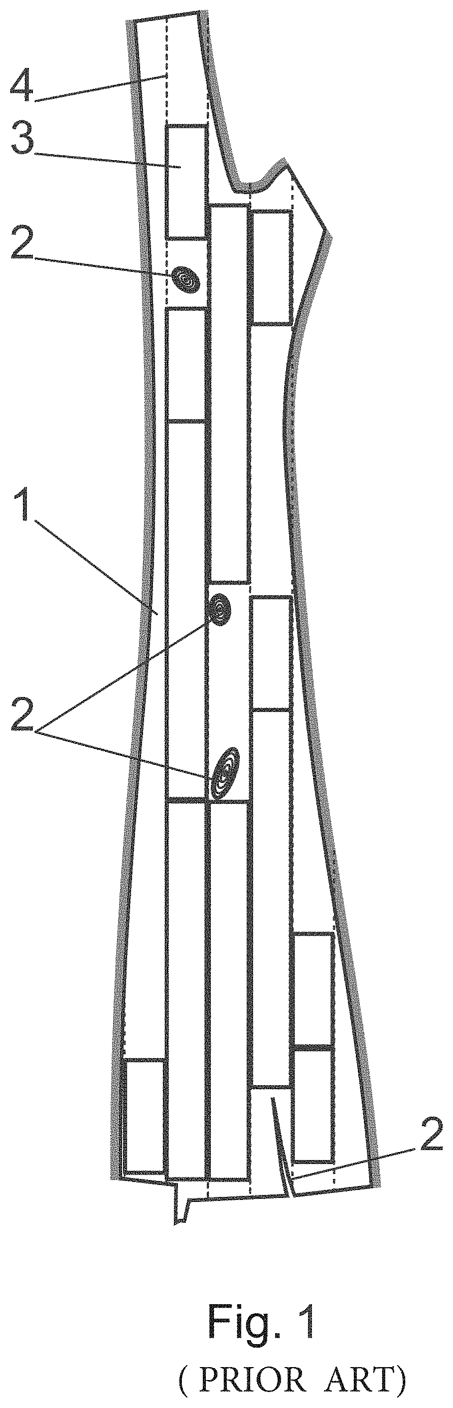
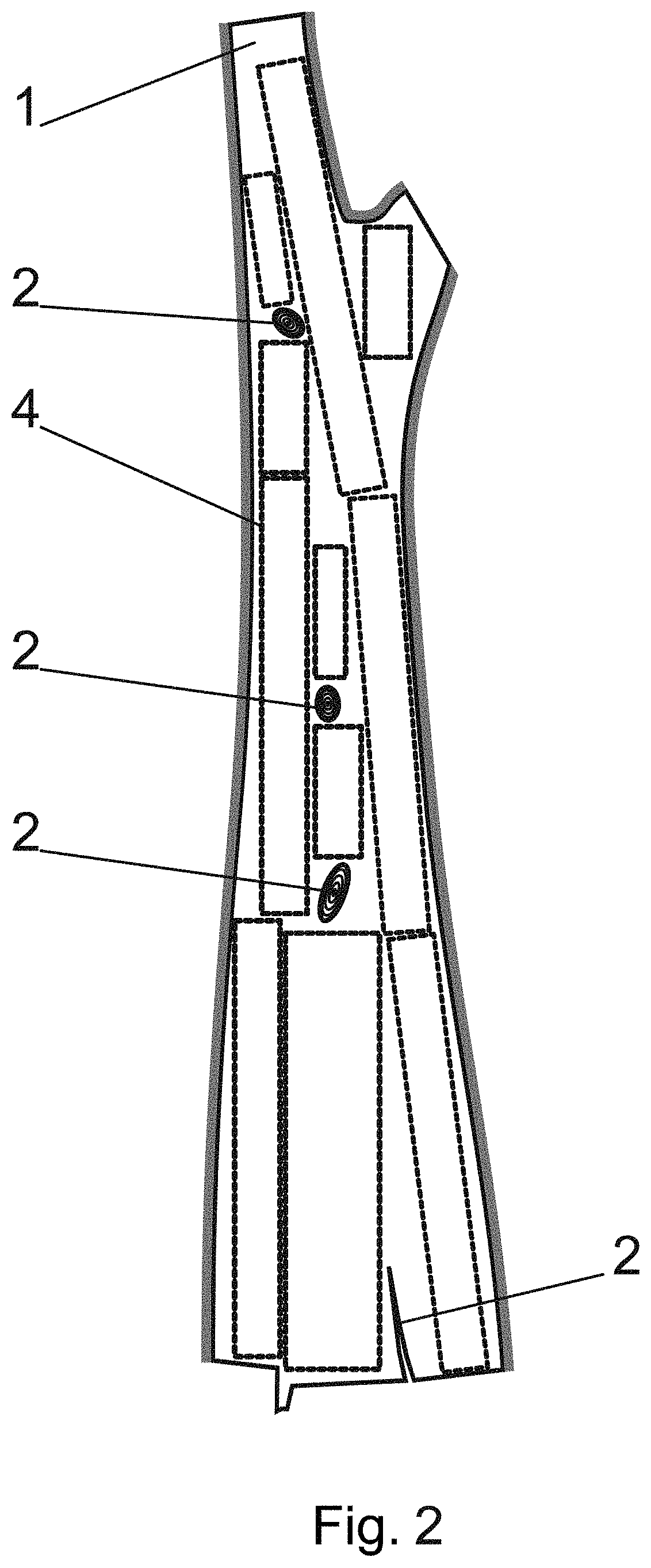
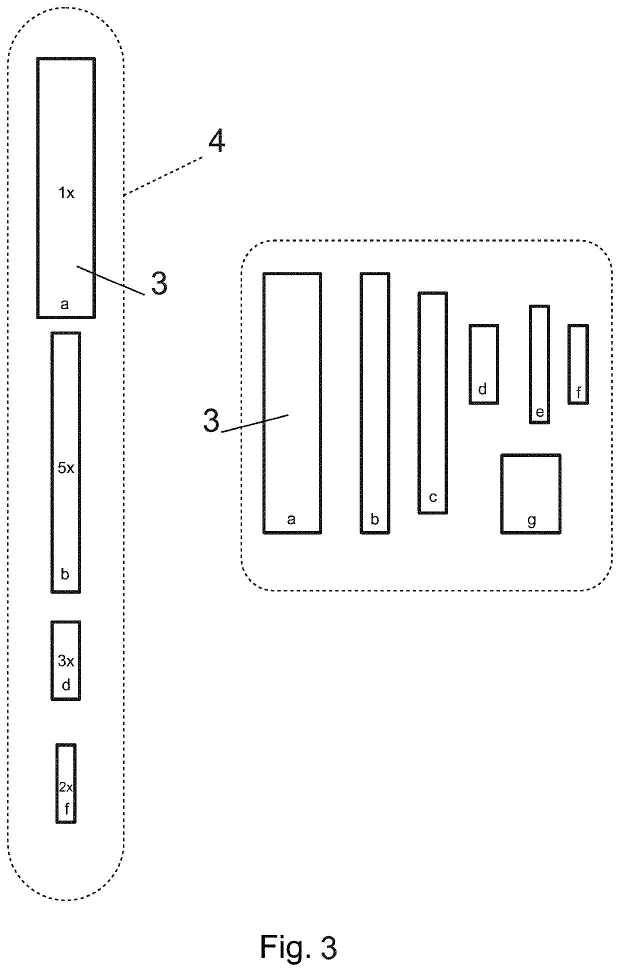
[0040]In this example according to FIGS. 2 and 3 is a method and system used at wood processing enterprise. The debranched trunks of the hardwood trees are cut to planks with the width which corresponds to the width of the products of one set of the desired shapes and dimensions of the products 3.

[0041]In this example the debranched trunk of the tree is after the basic peeling off of the bark cut by a set of the circular saws to the width 25 mm. This creates the plates on the surface of which there are defects 2 such as knots, cracks or zones with mechanical or biological damage. These defects 2 can be recognized on the basis of the optical analysis.

[0042]The scanner 5 is placed above the working table of the cutting machine 6. The working table moves in two directions; during scanning the working table moves in one direction and the plank placed on the working table runs under the scanner 5.

[0043]When scanning the surface of the visible side of the plank the gathered image is analy...

example 2

[0047]System in this example according to FIGS. 4 and 5 is concerned by the classification of the defects 2 in such a way that the acceptable defects 2 can appear on the resulting final products 3. On the scanner's 5 output there is a file which describes the outer boundaries of the scanned surface S and it discloses the boundaries of the recognized defects 2 alongside their classification into sets. Each defect is marked by category E_C[i] except for polygon E_P[i]; the number of categories is chosen pursuant to the nature of the material 1 and the clients' demands.

[0048]One of the sets contains unacceptable defects 2 such as cracks running through a whole width of the plank.

[0049]In this example the value of the residual material Crest is taken into account during optimalization, too.

[0050]The list of the desired products 3 has a structure with the parameters W[j], L[j], C[j] (width, length, weight coefficient) and A_E[j, x], which denotes the acceptability of the defect 2 defined...

example 3

[0057]The system in this example according to FIGS. 2 to 5 and 7 uses a CT scanner 8, too, by which the inside of the material 1 is radiologically investigated.

[0058]The material 1 runs between two suppliers which secure the regular movement of the material 1 and they produce a free space between them for the placement of the optical scanner 5 and CT scanner 8.

[0059]The scanner 5 allows for scanning of the surface from all sides; it has scanning strip with a given optics and it has cameras placed from above, from below and from sides. The complete surface of the material 1 is scanned within a single drag of the material 1. A CT scanner 8 with a shielding cover is placed behind the optical scanner 5. The X-ray runs through the material under various angles; the detectors analyze the impacting radiation and the computer creates an image in the scanned cross-section. The output from the CT scanner 8 is connected to the controlling computer 7, where the data from the optical scanning ar...


PUM

PropertyMeasurementUnit
widthaaaaaaaaaa
dimensionsaaaaaaaaaa
optical scanneraaaaaaaaaa

Abstract

When cutting the flat products (3) a set of the desired shapes and dimension of the products (3) is defined. Firstly at least one surface of the material (1) is scanned; scanning sets the boundaries of the available surface of the material (1). Optical scanning can be supplied by radiological scanning, preferably by a CT scanner (8). Defects (2) are identified in the scanned image and a position is assigned to them. A weight coefficient is assigned to each element from a set of the desired shapes and dimensions of the products (3). A cutting plan (4) is created; this plan (4) defines the boundaries of individual flat products (3), whereby the places with the identified defects (2) of the material (1). Optimalization of the distribution of the desired products (3) is realized with the goal of achieving the highest sum of the number of the products (3) multiplied by the weight coefficient of a given product (3) without the need to cut all the elements from a set of the desired products (3). Subsequently a cutting machine (6) is used to cut the products (3); this machine (6) cuts the material (1) without any limitation with regard to the mutual position of the cut lines of the neighboring products (3).

Description

CROSS REFERENCE TO RELATED APPLICATION[0001]This application is a national stage entry of PCT / 162016 / 055080 filed Aug. 25, 2016, under the International Convention claiming priority over Slovakia Patent Application No. PP 50044-2015 filed Aug. 25, 2015.FIELD OF THE INVENTION[0002]The invention concerns the optimalization of cutting of the flat products from the natural material which has or may have surface and / or internal irregularities or defects, whereby these irregularities are firstly detected and the cutting plan is devised taking these irregularities into account. The invention discloses a system for optimalized cutting of the flat natural intermediate products, mainly of wooden planks, stone plates, leather and so on.BACKGROUND OF THE INVENTION[0003]During the cutting of the homogenous materials an optimalization is used which ensures that the available material is used without the useless waste. One-dimensional optimalization during the division of the rod-like material suc...

Claims


Application Information

Patent Timeline
Patent Type & Authority Patents(United States)
IPC IPC(8): G05B19/402B26D5/00G05B19/401B27B1/00B26F1/38B23K26/402B23K26/382
CPCG05B19/402B26D5/00B26D5/007B26F1/3813B27B1/007G05B19/401B23K26/382B23K26/402G05B2219/31372G05B2219/35162G05B2219/35168
Inventor SCHMERINGA, PETER
Owner BIATEC GRP AS
Why Eureka
Try Eureka