AI technical title is built by Patsnap AI team. It summarizes the technical point description of the patent document.
a technology for counting objects and dispensers, applied in the field of counting objects, can solve problems such as and the inability to separate granules at the same time, so as to achieve the effect of preventing the granule from being broken and/or jammed in the dispenser
Active Publication Date: 2021-10-19
STIPLASTICS
View PDF49 Cites 2 Cited by
Summary
Abstract
Description
Claims
Application Information
AI Technical Summary
This helps you quickly interpret patents by identifying the three key elements:
Problems solved by technology
Method used
Benefits of technology
Benefits of technology
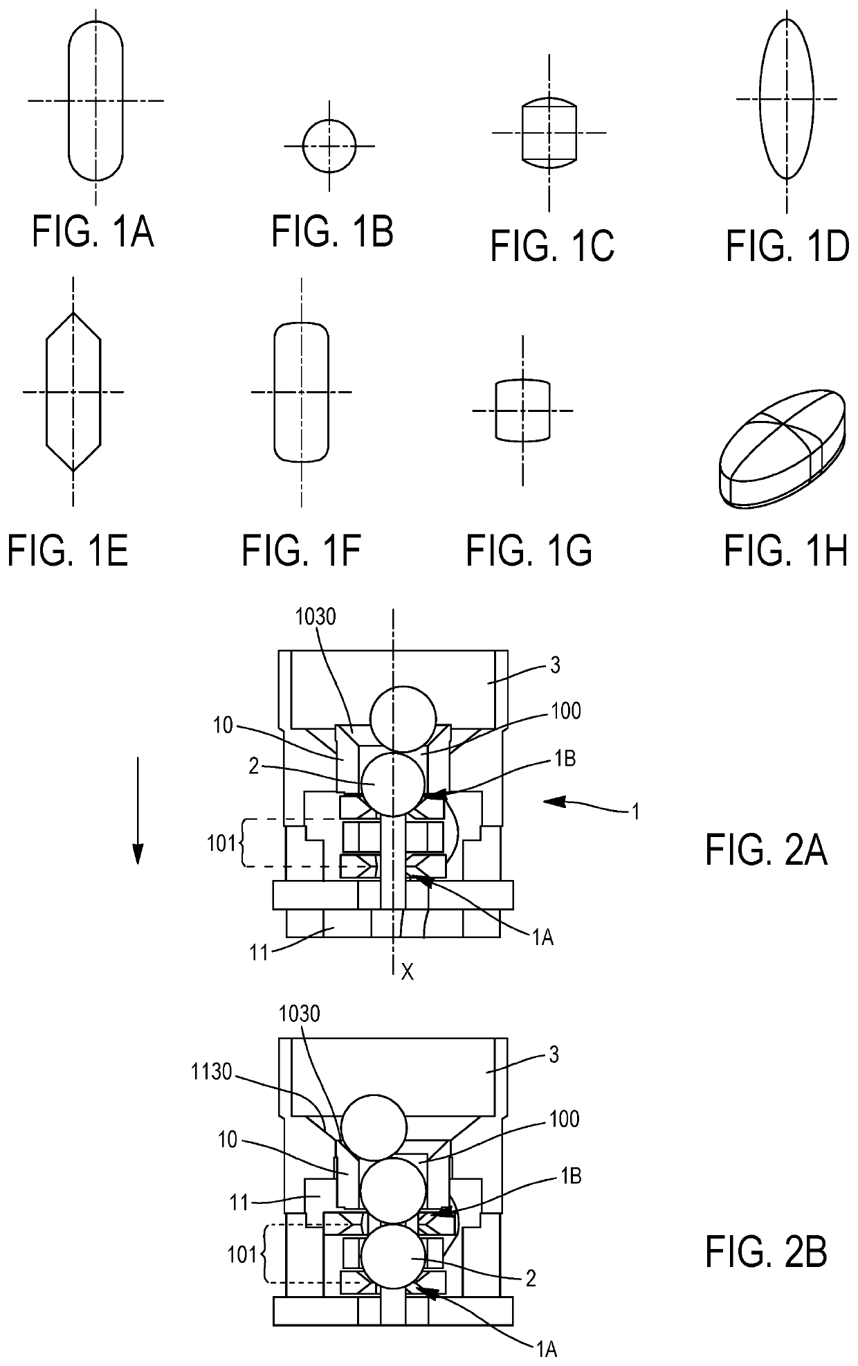
The invention is a device for counting and dispensing objects. The device aims to avoid common problems with existing dispensers, such as jamming and malfunction, while also minimizing damage to the objects. Additionally, the device allows for reliable and accurate counting of objects. The device can be manufactured with a reduced number of elements and methods compatible with large-scale production, making it economically competitive compared to existing devices. The design also utilizes bevelled shapes that prevent shearing of objects during use.
Problems solved by technology
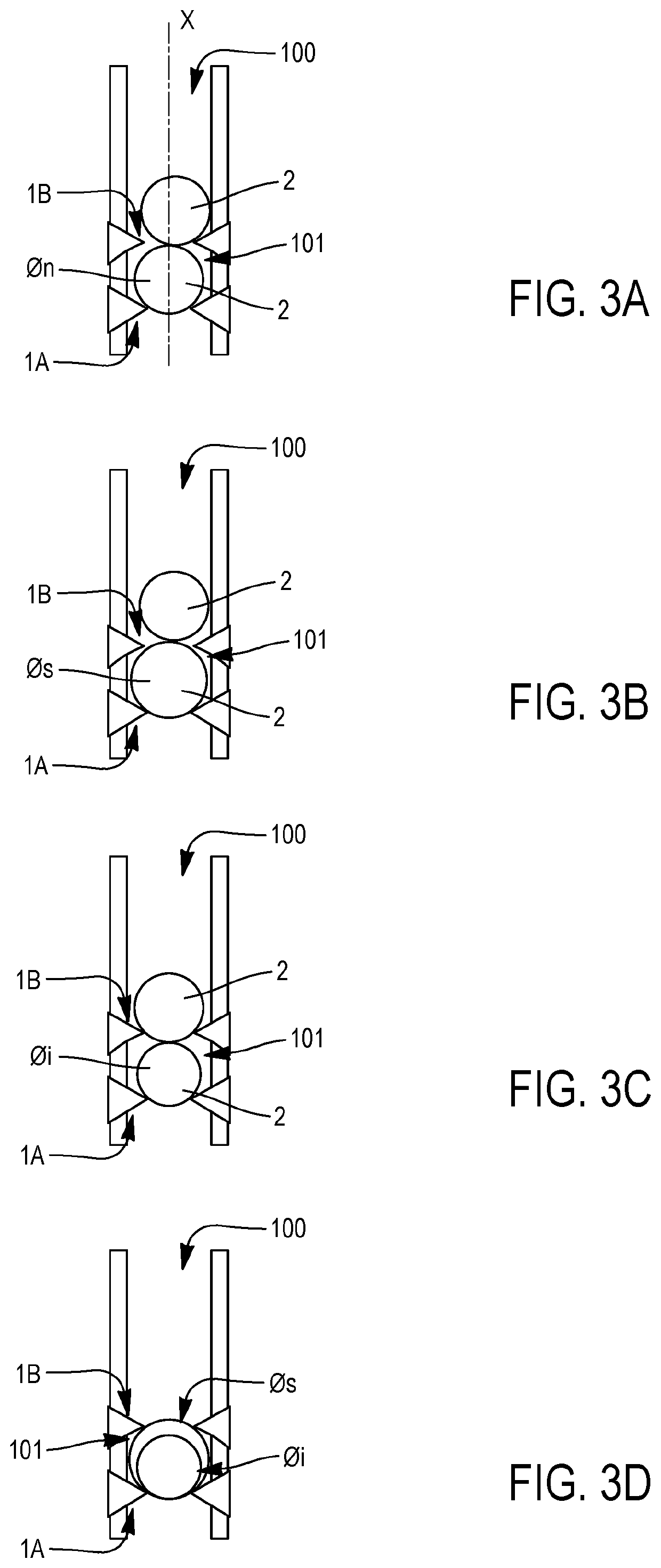
Therefore, in the presence of granules with a diameter larger than the rated diameter, there exists a risk that the granule be greater than the housing provided for receiving it, so that the setting into motion (rotation or translation) of the housing intended to transfer the granule from the tank to an outlet orifice exerts a shearing force on the granule, possibly inducing breakage of the granule and / or jamming of the dispenser.
Conversely, in the presence of granules of a diameter less than the rated diameter, the risk is that two granules simultaneously engage into the housing.
The setting into motion of the housing then exerts a great shearing force on the granule which is only partly engaged into the cell, which may then cause breakage of said granule and / or jamming of the dispenser.
In the particular case of tablets with a film, this breakage may be detrimental to the actual efficiency of the drug treatment, the active ingredients not having time for attaining their target.
In homeopathic applications, for which the grain size is generally not very controlled, a problem often encountered with existing dispensers is the absence of release of the expected granule at the end of the actuation sequence of the dispenser.
Method used
Image
Click on the blue label to locate the original text in one second.
Reading with bidirectional positioning of images and text.
Examples
first embodiment
[0095]a dispenser according to the invention will now be described with reference to FIGS. 5A to 5E. This dispenser is similar to the one illustrated in FIGS. 2A to 2D and in FIG. 4.
[0096]FIG. 5A is an exploded perspective view of both elements 10, 11 of the dispenser which cooperate for forming the obturators. The arrow indicates the direction of flow of the beads from upstream to downstream.
[0097]The element 11 has a generally tubular shape extending along the axis X and the wall of which is pierced with two parallel diametrically opposite grooves 112 which extend from the downstream edge of the element 11. The grooves 112 are not rectilinear but have two portions 112A, 112B tilted in opposite directions on either side of an inflection point 112C.
[0098]The wall of the element 11 is moreover pierced with two rectilinear grooves 113 diametrically opposite, parallel, which extends from the downstream side of the element 11.
[0099]The function of the grooves 112 and 113 will be explain...
second embodiment
[0124]With reference to FIGS. 6A to 6C, a dispenser according to the invention will now be described.
[0125]The dispenser 1 comprises an element 10 of a generally tubular shape extending along the axis X and the inner wall of which defines the conduit 100 for dispensing the beads. The wall of said element 10 comprises diametrically opposite apertures 107 and each surrounded by two protruding ribs 107A, 1078 from the outer wall of the element 10.
[0126]The dispenser moreover comprises an element 11 adapted for sliding on the element 10 in a direction perpendicular to the axis X while being guided between the ribs 107A, 107B.
[0127]For this purpose, the element 11 comprises two parallel arms 110, 111 which extend perpendicularly to the axis X, said arms 110, 111 being connected through a wall 114 extending in a plane perpendicular to said arms.
[0128]As this is better seen in FIG. 6B, each arm 110, 111 has a respective protrusion 110A, 111B (which is advantageously bevelled) facing the pr...
PUM
Abstract
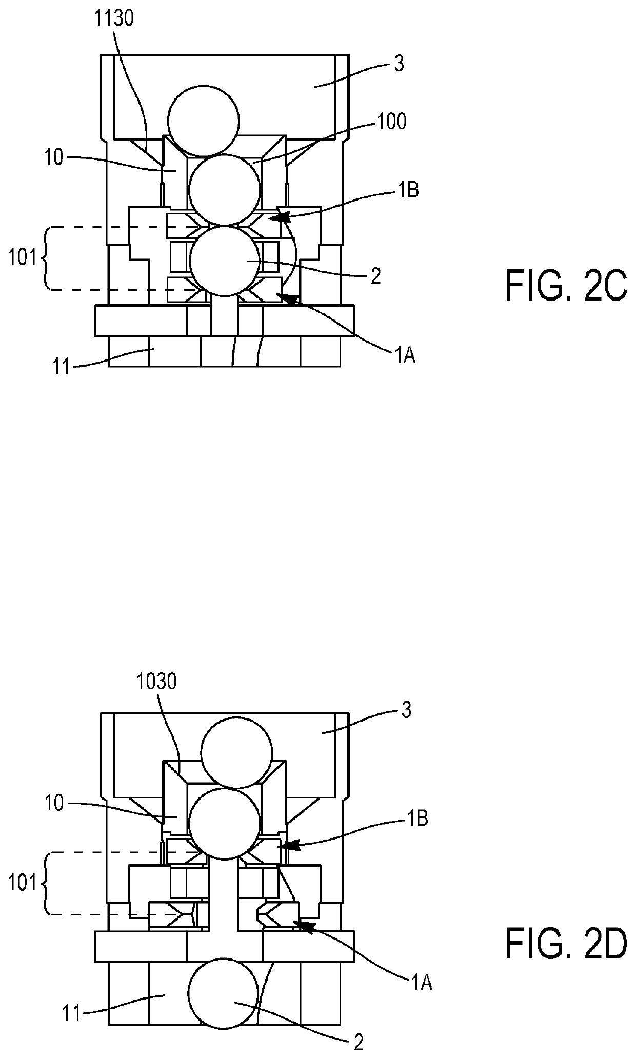
The invention relates to a device (1) for counting and dispensing objects (2), comprising two slidably movable elements (10, 11) relatively to each other,a first element (10) comprising a conduit (100) for dispensing objects to be counted and dispensed,the second element (11) cooperating with the first element for forming two obturators (1A, 1B) delimiting in the dispensing conduit (100) a chamber (101) adapted for containing a determined number of said objects,said obturators (1A, 1B) being able to adopt, depending on the relative position of said first and second elements:an open configuration, in which the obturator defines an orifice with a dimension adapted for letting through an object to be counted and dispensed, andan obturation configuration, wherein said orifice has an insufficient dimension for letting through an object,the first and second elements being laid out for providing, by relative sliding, an operating sequence of the obturators wherein:(i) a first obturator is in an open configuration while the second obturator is in an obturation configuration,(ii) the obturators are both in an obturation configuration,(iii) the first obturator is in an obturation configuration while the second obturator is in an open configuration,(iv) the obturators are both in an obturation configuration.
Description
CROSS REFERENCE TO RELATED APPLICATIONS[0001]The present application is a national phase entry under 35 U.S.C. § 371 of International Application No. PCT / EP2015 / 052972, filed Feb. 12, 2015, which claims priority from French Patent Application No. 1451065, filed Feb. 12, 2014, the disclosures of which are incorporated by reference herein.FIELD OF THE INVENTION[0002]The invention relates to a device for counting and dispensing objects such as beads, granules, micro-granules, tablets or capsules, and to a container containing such objects and comprising such a device, notably a tube of homeopathic granules.BACKGROUND OF THE INVENTION[0003]Within the scope of homeopathic treatment for example, a determined number of granules have to be administered to a patient, without said granules being directly handled by the patient.[0004]A certain number of dispensers have thus been developed with view to issuing a determined number of granules.[0005]Document EP 0 002 403 describes a dispenser of ...
Claims
Application Information
Patent Timeline
Application Date:The date an application was filed.
Publication Date:The date a patent or application was officially published.
First Publication Date:The earliest publication date of a patent with the same application number.
Issue Date:Publication date of the patent grant document.
PCT Entry Date:The Entry date of PCT National Phase.
Estimated Expiry Date:The statutory expiry date of a patent right according to the Patent Law, and it is the longest term of protection that the patent right can achieve without the termination of the patent right due to other reasons(Term extension factor has been taken into account ).
Invalid Date:Actual expiry date is based on effective date or publication date of legal transaction data of invalid patent.

