Control method for light therapy device

a control method and light therapy technology, applied in light therapy, radiation therapy, therapy, etc., can solve the problems of inability to achieve the purpose of treatment, damage to the illuminated portion, and inability to obtain a suitable light dose for the tissue of the illuminated portion, etc., to achieve the effect of effectively treating the illuminated portion

Active Publication Date: 2021-11-02
GCSOL TECH
View PDF23 Cites 0 Cited by
  • Summary
  • Abstract
  • Description
  • Claims
  • Application Information

AI Technical Summary

Benefits of technology

[0005]In view of the above, the primary objective of the present disclosure is to provide a control method of a light therapy device, thereby light emitted from the light therapy device could effectively treat an illuminated portion.

Problems solved by technology

However, since the light is transmitted under the skin surface of the human body, the light interacts with the tissue under the skin surface to absorb, scatter, refract, etc., so that the tissue of the illuminated portion cannot obtain a suitable light dose.
With too lower light dose, the purpose of treatment cannot be achieved; with too high light dose, the illuminated portion may be damaged.

Method used


Image

  • Control method for light therapy device
  • Control method for light therapy device
  • Control method for light therapy device

Examples


first embodiment

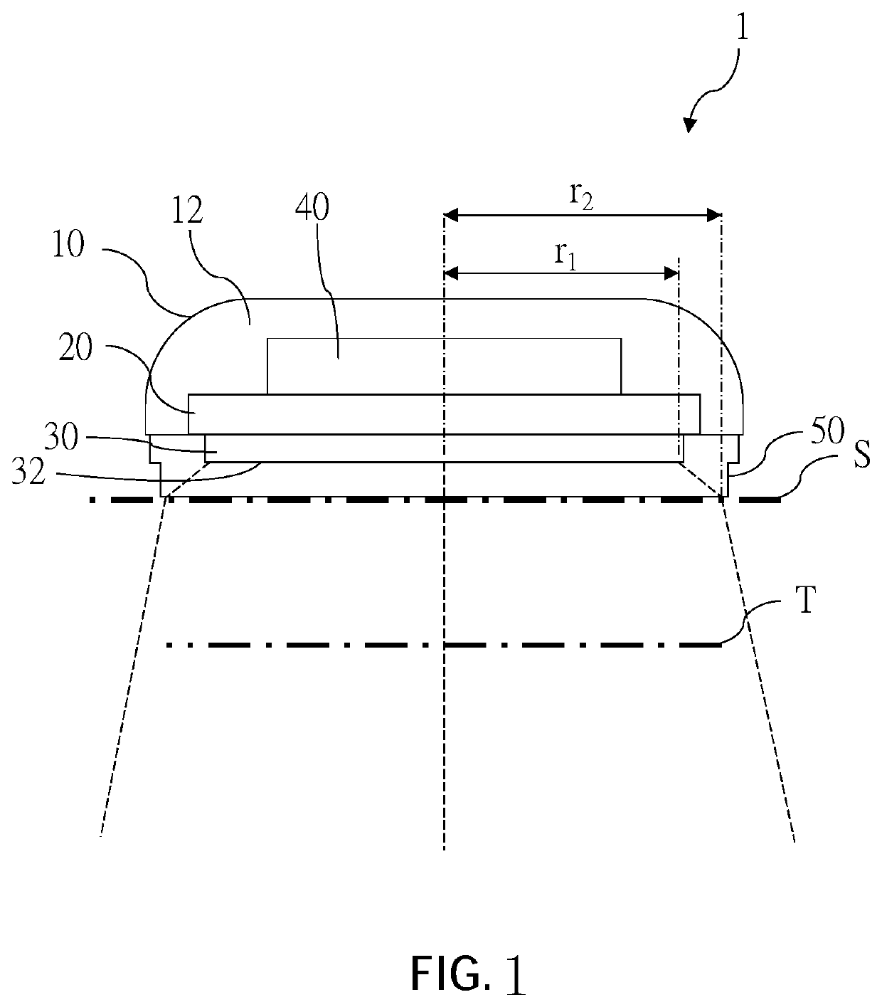
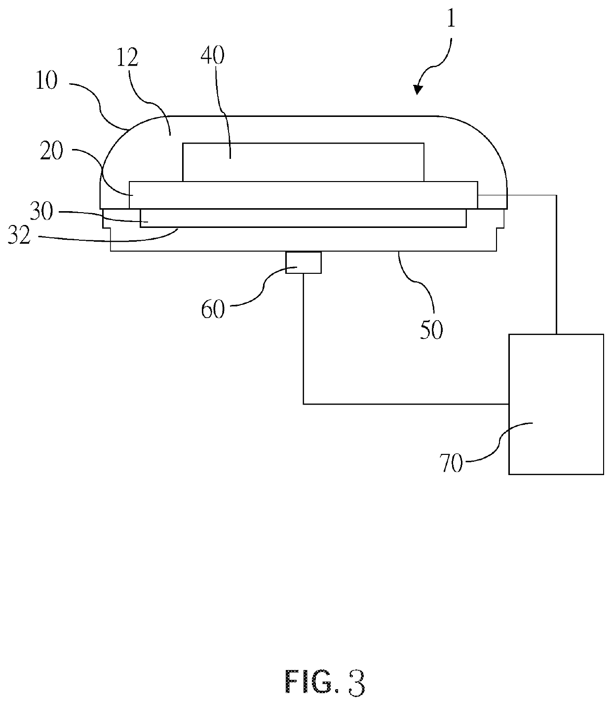
[0019]A control method for a light therapy device according to the present disclosure is applied to a light therapy device 1 illustrated in FIG. 1, wherein the light therapy device 1 includes a body 10, a control circuit 20, a light source 30, a battery 40, and a uniform light cover 50.

[0020]The body 10 has a receiving space 12 inside. The control circuit 20 is disposed in the receiving space 12 of the body 10. The light source 30 is engaged with a side of the control circuit 20, and has a light-emitting surface 32. In the current embodiment, the light source 30 includes a plurality of light-emitting diodes (LEDs), wherein each of the LEDs is a red LED with a wavelength of 600 nm-650 nm. The light-emitting surface 32 is an equivalent light-emitting surface formed by the LEDs. The control circuit 20 is controllable to adjust a light intensity outputted by the light source 30. The battery 40 is connected to another side of the control circuit 20 for supplying electricity to the contro...

third embodiment

[0042]A light therapy device 3 according to the present disclosure is illustrated in FIG. 5, which has almost the same structure as that of the aforementioned embodiments, except that the light therapy device 3 is a hand-held light therapy device, and includes a handle 80 which is adapted to be held by a user. In addition, the light therapy device 3 is not abutted against the skin surface S. Since a distance between the light therapy device 3 and the skin surface S varies with different usage habits, in order to keep the illumination corresponding to the skin surface S above the illuminated portion T fixed, thereby to allow the illuminated portion T under the skin surface S to be exposed to a suitable light dose, in the current embodiment, the light therapy device 3 further includes a light detector 82 electrically connected to the control circuit 20, wherein the light detector 82 is adapted to detect an illumination on the skin surface S above the illuminated portion T and sends th...


PUM

PropertyMeasurementUnit
distanceaaaaaaaaaa
red light wavelengthaaaaaaaaaa
light intensityaaaaaaaaaa

Abstract

A control method for a light therapy device, including steps of: set a light dose range (1-4J / cm2) required by an illuminated portion under a skin surface; calculate an appropriate intensity range outputted by a light source based on the set light dose, an illuminated time, and a proportion of light beam shape variation between the light source and the skin surface; build a corresponding relation between the appropriate intensity range and an ideal illumination range for the skin surface; measure an illumination of the skin surface, and monitor an output light intensity of the light source based on the illumination, ensuring that a light intensity outputted by the light source is a set ideal light intensity whereby, a light dose transmitted from the light therapy device to the illuminated portion could be kept in the set light dose by simply controlling the illumination to be within the set illumination range.

Description

BACKGROUND OF THE INVENTIONTechnical Field[0001]The present disclosure relates to a light therapy device, and more particularly to a control method for a light therapy device.Description of Related Art[0002]With the advancement in medicine and technology, a light therapy device has been developed recently, which uses light to illuminate an illuminated portion of a human body (e.g. a hypodermis or a tissue under a skin surface) to induce a biological response to the human body for therapeutic purposes. The light therapy device is a non-invasive treatment, and is a very safe treatment compared to invasive treatments such as acupuncture.[0003]A conventional method of controlling the light therapy device to illuminate to the illuminated portion of the human body by simply controlling the light source to output a certain light intensity and controlling an illuminated time. However, since the light is transmitted under the skin surface of the human body, the light interacts with the tissu...

Claims


Application Information

Patent Timeline
Patent Type & Authority Patents(United States)
IPC IPC(8): A61N5/06A61N5/067
CPCA61N5/062A61N5/067A61N2005/0626A61N2005/0652A61N2005/0659A61N2005/0661A61N5/06A61N2005/0642A61N2005/0627A61N2005/0651
Inventor PAI, JUI-FENKUO, CHEN-PING
Owner GCSOL TECH
Why Eureka
Try Eureka