Vehicle seat

a technology for vehicles and seats, applied in vehicle arrangements, vehicle heating/cooling devices, seat heating/ventilation devices, etc., can solve the problems of high manufacturing cost, reduced service life, and disadvantageous foot impact of rear seat occupants, etc., and achieve the effect of reducing the impact more reliably

Active Publication Date: 2021-11-09
TS TECH CO LTD
View PDF38 Cites 4 Cited by
  • Summary
  • Abstract
  • Description
  • Claims
  • Application Information

AI Technical Summary

Benefits of technology

[0005]In typical known embodiments where two or more seats arranged adjacently left and right have their individual blowers provided one for each seat, high manufacturing costs would be a problem to be resolved.
[0117]With this configuration, the portion of the duct routed at the rear side of the back side frame can be located at a higher position as compared with an alternative configuration in which the duct is routed at the rear side of the back side frame from the vicinity of the linking portion by which the cushion side frame and the back side frame are linked, and is connected to the seat back. Accordingly, the duct can be restrained more reliably from being hit by a foot of a rear-seat occupant.

Problems solved by technology

In some embodiments where the duct is made up of a plurality of parts connected to each other, a connected section of the duct at which such duct parts are connected would possibly be hit, for example, by a foot of a rear-seat occupant, or otherwise subjected to an impact, which in turn would disadvantageously cause the connected section to become broken off.
In typical known embodiments where two or more seats arranged adjacently left and right have their individual blowers provided one for each seat, high manufacturing costs would be a problem to be resolved.
In some embodiments known in the art where the duct is laid or routed in such a manner as to extend out from a rear end of the seat cushion toward the seat back, the duct would disadvantageously be hit by a foot of a rear-seat occupant.

Method used


Image

  • Vehicle seat
  • Vehicle seat
  • Vehicle seat

Examples


first embodiment

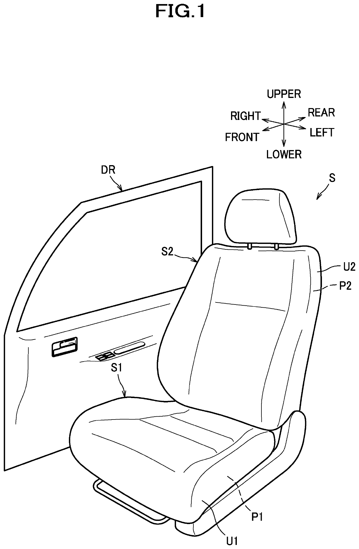
[0172]Hereinafter, a description will be given of a first embodiment with reference made to accompanying drawings. In this description, the front / rear (frontward / rearward), left / right (leftward / rightward; lateral), and upper / lower (upward / downward; vertical) are represented with reference to the front / rear, left / right, and upper / lower directions as viewed from a person seated on the seat.

[0173]As shown in FIG. 1, a vehicle seat of the present embodiment is configured as a car seat S to be installed in an automobile, and includes a seat cushion S1 and a seat back S2.

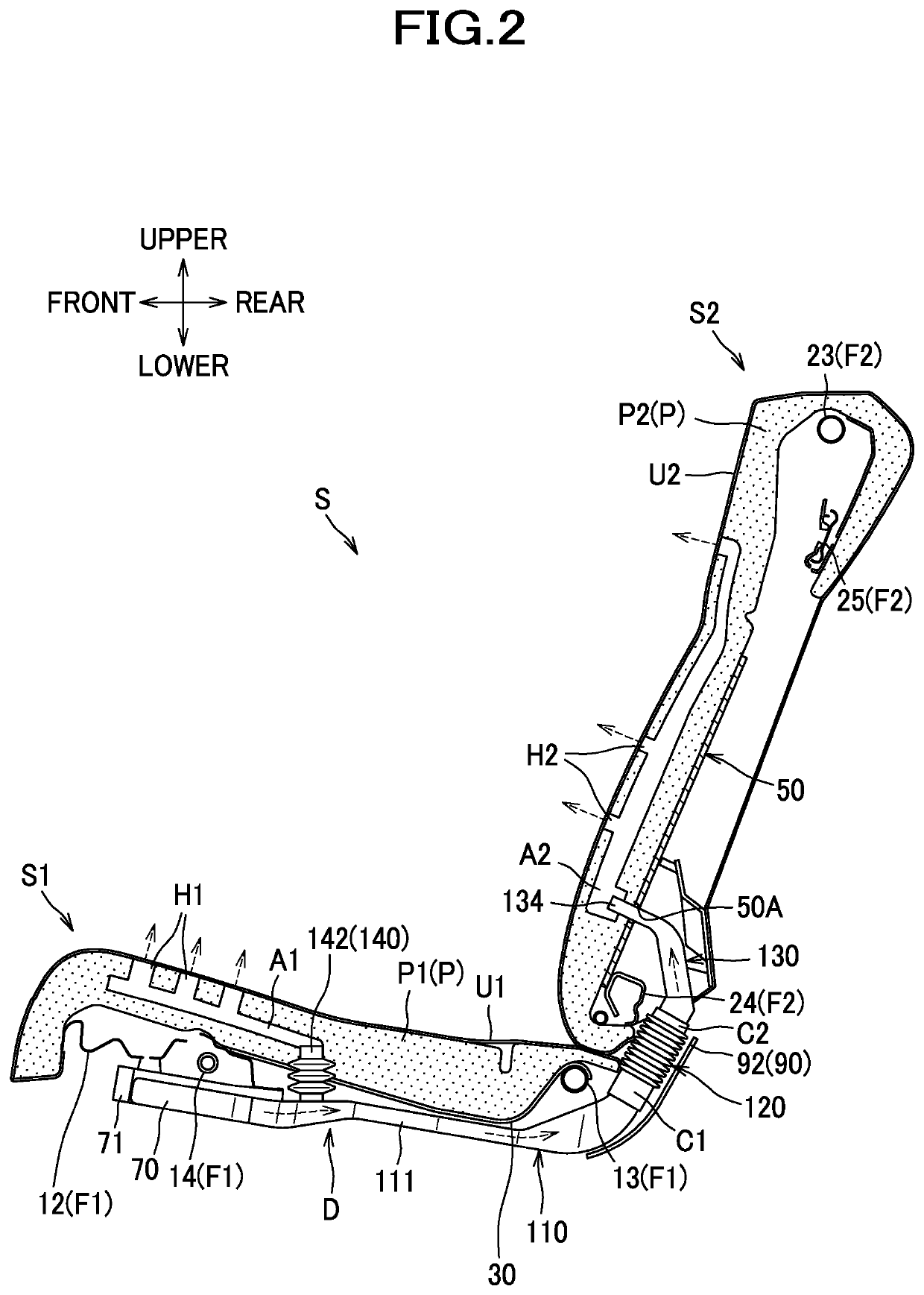
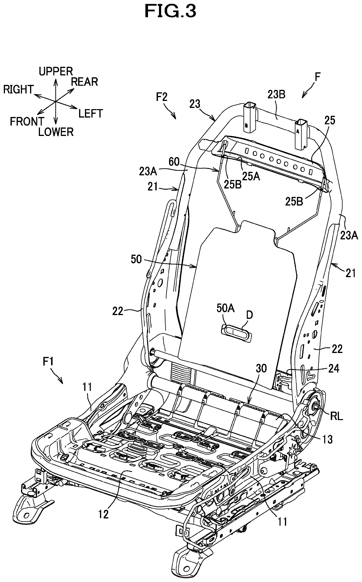
[0174]As shown in FIG. 2, the car seat S is constructed of a seat frame F (see FIG. 3) upholstered with a pad P made of urethane foam or the like and outer coverings U1, U2 made of fabrics, leather or the like.

[0175]The pad P includes a cushion pad P1 constituting a pad for a seat cushion S1, and a back pad P2 constituting a pad for a seat back S2. The cushion pad P1 has an air passage A1 formed therein, and a plurality o...

second embodiment

[0218]Next, a description will be given of a Hereinafter, the same structural features as those of the embodiment described previously are designated by the same reference numerals and an explanation thereof will be omitted where appropriate, and the features different from those of the embodiment described previously will be explained in detail.

[0219]As shown in FIG. 10, a vehicle seat of the present embodiment is configured as a car seat S installed in an automobile, and includes a first seat portion S10 and a second seat portion S20. The first seat portion S10 and the second seat portion S20 are located left and right adjacent to each other without intervening space.

[0220]The first seat portion S10 includes a first seat cushion S11 and a first seat back S12. The first seat portion S10 also includes a first headrest S13 and a third headrest S14.

[0221]The second seat portion S20 includes a second seat cushion S21 and a second seat back S22. The second seat portion S20 also include...

third embodiment

[0264]A description will be given of a

[0265]As shown in FIG. 16, a car seat S comprises a seat frame F (see FIG. 17) upholstered with a pad P and outer coverings U1, U2. The pad P and the seat frame F are configured generally in a manner similar to that in which the relevant features of the car seat S in the first embodiment are configured.

[0266]As shown in FIG. 17, the back frame F2 includes left and right sheet-metal frames 22, a pipe frame 23, a lower frame 24 as a lower frame, and a bridging frame 25.

[0267]A rear portion of the cushion side frame 11 and a lower portion of the back side frame 21 are rotatably linked via a reclining mechanism RL.

[0268]As shown in FIG. 18, the duct D includes a plurality of parts connected to each other. To be more specific, the duct D includes a first duct member 210 as a first part, a second duct member 220 as a second part and a third part, a third duct member 230 as a fourth part, and a fourth duct member 140.

[0269]The first duct member 210 inc...


PUM


Abstract

Provided is vehicle seat with a seat cushion and a seat back, the vehicle seat comprising: a duct disposed astride the seat cushion and the seat back, and configured to connect an air passage and a blower, the air passage being formed in the seat cushion and the seat back; and a side frame cover configured to cover part of the duct. The duct includes a first duct member and a second duct member connected to the first duct member. The side frame cover is configured to cover at least part of a first connected section that is a section at which the first duct member and the second duct member are connected.

Description

TECHNICAL FIELD[0001]The present invention relates to a vehicle seat with a seat cushion and a seat back.BACKGROUND ART[0002]There is hitherto known in the art a car seat which comprises a seat cushion and a seat back having outlet openings and air passages formed therein, a blower attached to a bottom surface of the seat cushion, and a duct connecting the blower and an air passage of the seat back wherein conditioned air is forced by the blower through the air passages and the duct to the outlet openings (Patent document 1).CITATION LISTPatent Literature[0003]Patent Document 1: JP 2009-023477 ASUMMARY OF INVENTION[0004]In some embodiments where the duct is made up of a plurality of parts connected to each other, a connected section of the duct at which such duct parts are connected would possibly be hit, for example, by a foot of a rear-seat occupant, or otherwise subjected to an impact, which in turn would disadvantageously cause the connected section to become broken off.[0005]In...

Claims


Application Information

Patent Timeline
Patent Type & Authority Patents(United States)
IPC IPC(8): B60N2/56B60H1/00
CPCB60N2/5628B60N2/5657B60H1/00285B60N2/22B60N2/5635
Inventor HOSHI, YUICHIROKOBAYASHI, KAZUKIKONNO, TATSUMI
Owner TS TECH CO LTD
Why Eureka
Try Eureka