Vehicle shifter device

a shifter and vehicle technology, applied in the direction of control devices, gearing control, gearing elements, etc., can solve the problem of driving the driver to perform a complicated operation, and achieve the effect of suppressing a misoperation and high security

Active Publication Date: 2021-11-09
MAZDA MOTOR CORP
View PDF13 Cites 1 Cited by
  • Summary
  • Abstract
  • Description
  • Claims
  • Application Information

AI Technical Summary

Benefits of technology

[0006]The disclosure thus provides a vehicle shifter device capable of ensuring a high level of security by suppressing a misoperation by the driver.
[0008]In the vehicle shifter device according to the aspect, since the path of the movement of the upper end part (part grasped by the driver for operation) of the shift lever during a switchover among the reverse (R) range, the neutral (N) range, and the drive (D) range is different in direction from the path of the movement of the upper end part during the switchover between the parking (P) range and the R-range, the difference in the operational direction of the shift lever suppresses an undesirable operation by the driver such as a switchover among speed ranges from the R-range to the P-range or an undesirable operation from the P-range to the D-range directly.
[0010]Accordingly, the vehicle shifter device according to the aspect suppresses a misoperation by the driver and ensures a high level of security.
[0024]The vehicle shifter devices described above can ensure a high level of security by suppressing a misoperation by the driver.

Problems solved by technology

However, in the vehicle shifter device disclosed in JP-A-2007-253912, since the R-position and the D-position need to be selected by operating the shift lever and the P-position and the N-position need to be selected by operating the push button disposed away from the shift lever, the driver is requested to perform a complicated operation.
Such a misoperation during a switchover among speed ranges becomes a large problem in the driving of a vehicle that requires a high level of security.

Method used


Image

  • Vehicle shifter device
  • Vehicle shifter device
  • Vehicle shifter device

Examples


embodiment

1. Structure of Vehicle Interior 2 of Vehicle 1

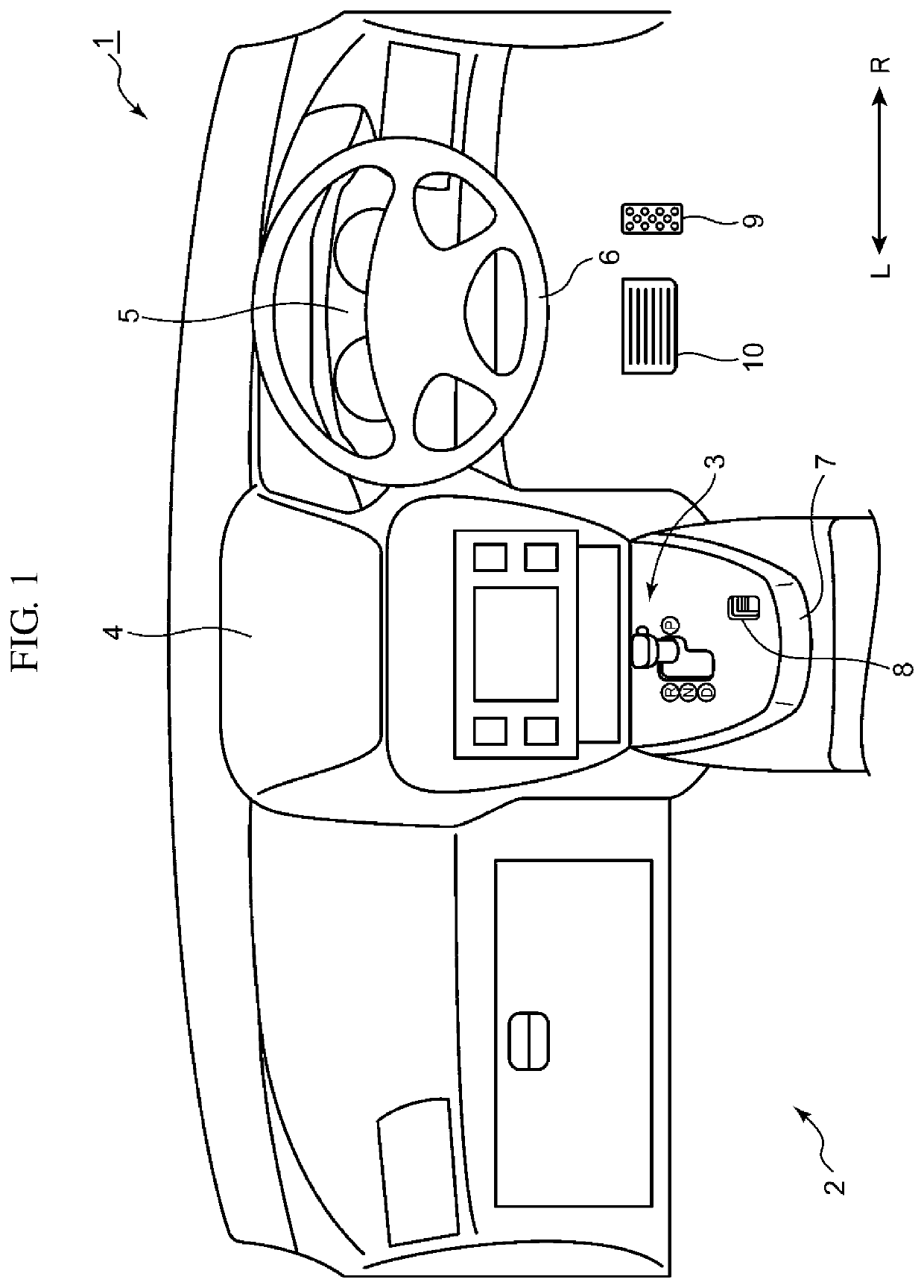
[0038]The structure of a vehicle interior 2 of a vehicle 1 will be described with reference to FIG. 1.

[0039]As illustrated in FIG. 1, a meter unit 5 of an instrument panel 4 and a steering handle 6 are disposed in front of the location in which a driver sits. The meter unit 5 displays a speed, engine revolutions, a gear range, and the like.

[0040]An acceleration pedal 9 and a brake pedal 10 are disposed in a foot part in front of the driver. A center console 7 is provided between a driver seat and a passenger seat. The center console 7 is provided so as to extend in a front-rear direction of the vehicle and an upper surface thereof is formed substantially flat so that the driver can place an arm thereon.

[0041]The center console 7 is provided with a vehicle shifter device 3 and a parking switch 8. The driver causes an automatic transmission (not illustrated) of the vehicle 1 to perform a switchover among a plurality of speed ranges by ope...


PUM


Abstract

A vehicle shifter device for ensuring high safety by suppressing misoperation by a driver. The vehicle shifter device includes a shift lever and a lock plate. The shift lever has a cylindrical lever body, a rod movable in an axial direction in a cylinder of the lever body, and a first lock lever and a second lock lever connected to the rod. The first lock lever is substantially L-shaped in plan view. The lock plate has a first extension portion extending in an X-direction and a second extension portion, integrally formed with the first extension portion, that extends in a Y-direction. In addition, the lock plate has a plurality of concave parts. In the lock plate, the projection height of a convex part between the concave part and the concave part is larger than the projection height of a convex part between the concave part and the concave part.

Description

BACKGROUNDTechnical Field[0001]The present disclosure relates to a vehicle shifter device.Background Art[0002]A vehicle shifter device is provided in a center console or an instrument panel to receive an input concerning a switchover among speed ranges from a driver. An example of a vehicle shifter device is a mechanical vehicle shifter device that is mechanically connected to an automatic transmission via a cable or the like or a so-called shift-by-wire vehicle shifter device that performs a speed change by electrically detecting the position of a shift lever selected by the driver and sending information of the detected position to a control unit via an electric signal.[0003]Since the support structure of a shift lever can be small-sized in a shift-by-wire vehicle shifter device, the entire device can be small-sized.[0004]JP-A-2007-253912 discloses a vehicle shifter device that selects a reverse (R) position and a drive (D) position by operating a shift lever and selects or desele...

Claims


Application Information

Patent Timeline
Patent Type & Authority Patents(United States)
IPC IPC(8): F16H59/02F16H59/10F16H59/12F16H61/24
CPCF16H59/0278F16H59/105F16H59/12F16H2059/0282F16H2061/243F16H61/18B60K20/02F16H2061/185F16H2061/223F16H61/22F16H2059/026F16H59/10
Inventor YOHSUKE, TAKENAGANAKATA, DAIKIMATSUOKA, TOSHIHIROTOKUMO, MASAYUKI
Owner MAZDA MOTOR CORP
Why Eureka
Try Eureka