Fuse circuit and redundancy circuit

a fuse circuit and redundancy circuit technology, applied in the direction of digital storage, electrical equipment, instruments, etc., can solve the problems of ineffective disposal of semiconductor memory devices as defective products, inability to perform desired operations of semiconductor memory devices, and failure of a relatively small number of memory cells, so as to prevent the cracking of the fuse effect of semiconductor memory devices

Active Publication Date: 2010-11-18
SK HYNIX INC
View PDF4 Cites 1 Cited by
  • Summary
  • Abstract
  • Description
  • Claims
  • Application Information

AI Technical Summary

Benefits of technology

[0046]The present invention can detect a fuse including a crack by adjusting a critical voltage that is a reference voltage to detect a condition of a fuse in a test before the shipment. Since it is possible to repair the fuse where the crack is generated based on the detected results, undesirable operations of the semiconductor memory device by the crack of the fuse can be prevented.

Problems solved by technology

However, even if only one of the memory cells fails, the semiconductor memory device may not perform a desired operation.
As technology of fabricating the semiconductor memory device develops, a comparatively small number of memory cells may fail.
Accordingly, it is very ineffective to dispose the semiconductor memory device as a defective product due the failure of only few memory cells in the product yields.
However, since a space between lines or a space between circuits in the semiconductor memory device is being designed to be comparatively close in proportion to the increase of the integration, there occur various problems.
One such a problem is a crack generated in a fuse by a fuse cutting operation.
At this time, damage, e.g., a crack, occurs in the fuses A and C adjacent to the fuse B due to conductive by-products and an impact generated when performing the blowing process.
However, in the second case, since the crack is not detected in a test performed before the shipment of the semiconductor memory device and it causes a malfunction after the shipment of the semiconductor memory device, a user of the semiconductor memory device may be presented with a problem.
However, after the shipment of the semiconductor memory device, the fuse F having the crack is getting deteriorated according to the environment and the time and thus falls into a condition where it seems to be cut.
That is, the semiconductor memory device operates undesirable due to the fuse F having the crack.
However, a conventional test may not detect the fuse F having the crack as defective.
However, after the shipment of the semiconductor memory device, the 10th fuse F10 having the crack gets worse according to the environment and the time and thus falls into a condition where it seems to be cut.
That is, the redundancy circuit is undesirably operated for the 10th fuse F10 having the crack and the repair information signal INF_REN generated thereby causes undesirable replacement of a normal memory cell with a redundancy memory cell.
As described above, a crack may be generated in a fuse by the cutting of a neighboring fuse, the processing failure, and the environment and the time, which causes undesirable operations in the typical fuse and redundancy circuits.
However, since a fuse having a progressive crack that is not comparatively serious is not detected in the test before the shipment, the fuse may cause various undesirable operations after the shipment.
As a result, a user may be presented with a problem and thus the reliability of a product may deteriorate.

Method used


Image

  • Fuse circuit and redundancy circuit
  • Fuse circuit and redundancy circuit
  • Fuse circuit and redundancy circuit

Examples


Embodiment Construction

[0060]Other objects and advantages of the present invention can be understood by the following description, and become apparent with reference to the embodiments of the present invention.

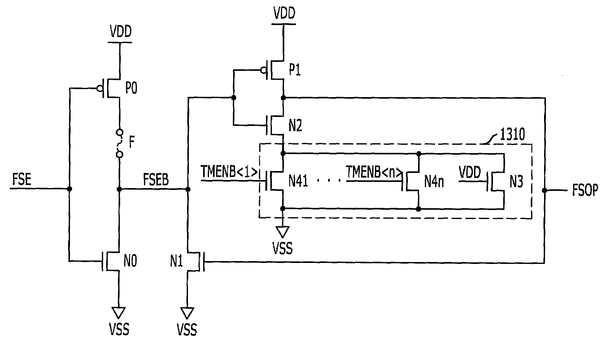
[0061]FIG. 10 illustrates a fuse circuit in accordance with an embodiment of the present invention.

[0062]Referring to FIG. 10, the fuse circuit includes a fuse block 1010 and a voltage detection block 1030.

[0063]The fuse block 1010 includes a 0th PMOS transistor P0, a fuse F and a 0th NMOS transistor N0 that are connected in series between an external supply voltage (VDD) terminal and a ground voltage (VSS) terminal, wherein a fuse enable signal FSE is provided to gates of the 0th PMOS transistor P0 and the 0th NMOS transistor N0. Herein, the fuse enable signal FSE transfers from a logic high to a logic low if a power-up operation of a semiconductor memory device is terminated and thus internal and external reset operations are terminated. Thus, the fuse block 1010 can drive its output node through ...


PUM


Abstract

A fuse circuit or a redundancy circuit is capable of detecting a fuse with a crack. The fuse circuit includes a fuse block configured to drive an output node through a current path including a fuse in response to a fuse enable signal, and a voltage detection block configured to detect a voltage level of the output node based on a critical voltage adjusted according to a test mode signal, thereby generating a fuse condition signal.

Description

CROSS-REFERENCE TO RELATED APPLICATIONS[0001]The present application claims priority of Korean Patent Application No. 10-2009-0041596, filed on May 13, 2009, the disclosure of which is incorporated herein by reference in its entirety.BACKGROUND OF THE INVENTION[0002]The present invention relates to semiconductor design technology, and more particularly, to a redundancy circuit and a fuse circuit, capable of performing various circuit operations using fuse(s).[0003]In general, as a degree of integration of a semiconductor memory device such as a double data rate synchronous dynamic random access memory (DDR SDRAM) device is increasing rapidly, tens of millions of memory cells are being included in one semiconductor memory device. However, even if only one of the memory cells fails, the semiconductor memory device may not perform a desired operation. As technology of fabricating the semiconductor memory device develops, a comparatively small number of memory cells may fail. Accordingl...

Claims


Application Information

Patent Timeline
Patent Type & Authority Applications(United States)
IPC IPC(8): G11C29/00H01H85/00G11C17/16
CPCG11C17/143G11C17/16G11C17/165G11C29/785G11C29/02G11C29/027G11C29/028G11C17/18G11C29/787
Inventor SONG, CHOUNG-KISHIN, HAN-SUB
Owner SK HYNIX INC
Why Eureka
Try Eureka