Control system for a vehicle suspension

a control system and vehicle technology, applied in the field of control systems, can solve problems such as increasing the height of the suspension

Active Publication Date: 2018-03-06
JAGUAR LAND ROVER LTD
View PDF59 Cites 4 Cited by
  • Summary
  • Abstract
  • Description
  • Claims
  • Application Information

AI Technical Summary

Benefits of technology

[0013]The suspension control means can be selectively operable to control said suspension units in a self-levelling mode. The inventors have recognised that operating the vehicle suspension system in a self-levelling mode is not desirable in all situations. When the self-levelling mode is active, the suspension control means will tend to respond to an unrequested increase in the suspension height by reducing the suspension height (for example reducing the fluid pressure in the suspension unit). However, this may reduce the ultimate wading depth capability of the vehicle; and / or reduce the reaction forces between the tyres and the ground, thereby reducing traction. Thus, if the unrequested suspension height change is a result of the vehicle wading, the operation of the suspension control means in said self-levelling mode may be undesirable. The control system can be configured to inhibit said self-levelling mode when said unrequested suspension height change is detected for at least one, two, three or four of said suspension units. The self-levelling mode can automatically be inhibited when the vehicle is wading. The control system can thereby help to reduce or avoid unnecessary and / or unwanted changes in suspension height.
[0030]The control means can be in communication with a traction control system to determine when traction is no longer available. The loss of traction can, for example, indicate that the vehicle wheels have been lifted, for example due to the buoyancy of the vehicle body or the underside of the vehicle being partially or completely grounded. If the traction control system determines that traction has been lost, the suspension control means can be configured to increase the height of one or more of said suspension units. The suspension control means can be configured to increase the height of the suspension unit where a loss of traction has been detected and / or a suspension unit disposed opposite to the suspension unit where the loss of traction has been detected (to pivot the vehicle body to improve traction). The control system can thereby be configured to provide progressive responses to wading detection. The control system can initially operate to inhibit the self-levelling mode to prevent unwanted reduction in suspension height; followed by an increase in the suspension height if traction is lost.
[0032]The suspension control means can actively control the height of the suspension units to adjust a ride height between sprung and unsprung parts of the vehicle. When operating in said self-levelling mode, the suspension control means can output height change signals to control the height of each suspension unit at a target height or within a target height range. The suspension control means can output height change signals to increase the suspension height when the suspension height is below a target height; and to decrease the suspension height when the suspension height is above a target height. The vehicle ride height can thereby be maintained at a target ride height. The control system can be configured to modify a target suspension height, for example in dependence on detection of a wading event or a belly out event.

Problems solved by technology

This can occur when the vehicle is wading since the inherent buoyancy will tend to lift the body, thereby increasing the suspension height.

Method used


Image

  • Control system for a vehicle suspension
  • Control system for a vehicle suspension
  • Control system for a vehicle suspension

Examples


Embodiment Construction

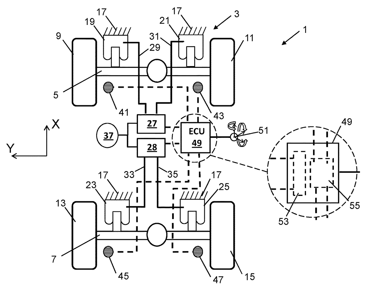
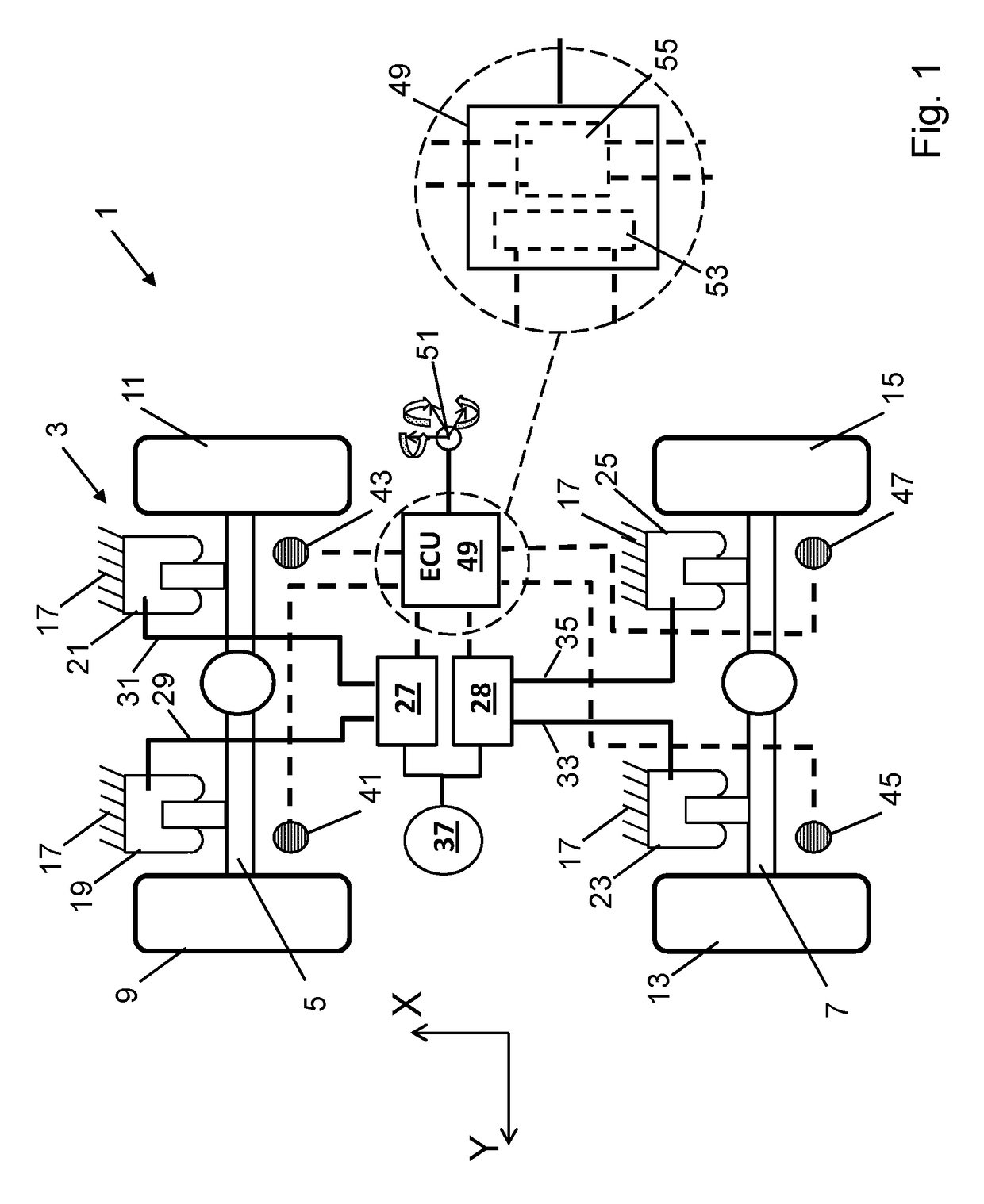
[0068]A vehicle 1 having an adjustable height suspension 3 in accordance with the present invention is illustrated in FIG. 1. The vehicle 1 is a four-wheel drive vehicle capable of driving off-road.

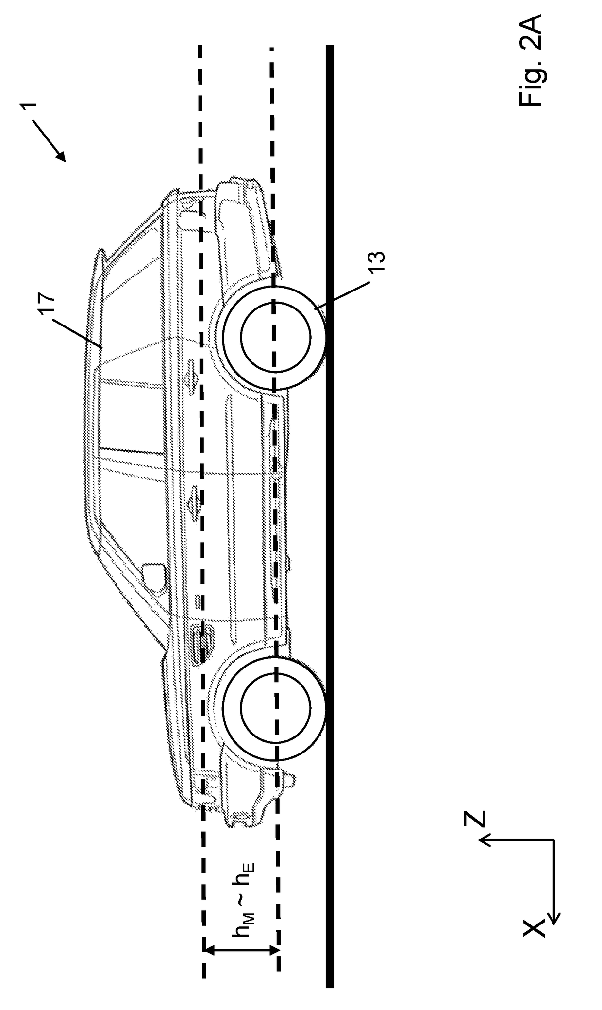
[0069]The vehicle 1 has a front axle 5 and a rear axle 7, both representing unsprung parts of the vehicle 1. The front axle 5 carries front wheels 9, 11; and the rear axle 7 carries rear wheels 13, 15. A sprung part of the vehicle 1, represented diagrammatically as a body or chassis 17 (see FIG. 2), has its weight supported by front air spring suspension units 19, 21 and rear air spring suspension units 23, 25.

[0070]The air spring suspension units 19, 21, 23, 25 are connected to respective front and rear valve blocks 27, 28 through individual pipes 29, 31, 33, 35. The valve blocks 27, 28 are connected to a motor driven compressor 37 through a regenerative dryer. The valve blocks 27, 28 comprises a valve array (not shown) which can operatively connect each air spring suspension unit 19, 21...


PUM


Abstract

The present application relates to a control system (49) for controlling a motor vehicle suspension (3). The suspension (3) has a plurality of adjustable height suspension units (19, 21, 23, 25) and a suspension control means (53) is provided to control the suspension units (19, 21, 23, 25). The control system (49) has a receiver for receiving height data form height sensors (41, 43, 45, 47) to provide height measurements for each suspension unit (19, 21, 23, 25). A suspension modelling means is provided for modelling the height of each suspension unit (19, 21, 23, 25). The control system (49) is configured to detect an unrequested suspension height change when the difference between the modelled height and the measured height of one or more suspension units (19, 21, 23, 25) exceeds a threshold. The present application also relates to a motor vehicle; and a method of detecting an unrequested suspension height change.

Description

TECHNICAL FIELD[0001]The present invention relates to a control system for controlling a motor vehicle suspension system; a suspension system; a motor vehicle; and a method of detecting an unrequested suspension height change.BACKGROUND OF THE INVENTION[0002]It is known to provide vehicle suspension systems with adjustable suspension units. A suspension controller can control the height of the suspension units to provide a self-levelling function whereby the height of each suspension unit is maintained at a target height. The suspension control unit will typically seek to increase the suspension height if it is lower than the target height; and decrease the suspension height if it is higher than the target height.[0003]A suspension system for a motor vehicle is known from EP 0900152 to make vehicle hang-ups less likely. The suspension system is operative to adjust the ride height between sprung and unsprung parts of the vehicle. A height sensor is provided for air springs within the...

Claims


Application Information

Patent Timeline
Patent Type & Authority Patents(United States)
IPC IPC(8): B60G17/016G06F7/00B60G17/0165B62C3/00B60G17/019B60G17/017
CPCB60G17/016B60G17/017B60G17/0165B60G17/019B60G2400/252B60G2300/07B60G17/0185B60G17/0195B60W10/22B60G2400/25B60G2400/51B60G2400/82
Inventor GUEST, PHILIP
Owner JAGUAR LAND ROVER LTD
Why Eureka
Try Eureka