Sequential projection color display using multiple imaging panels

a color display and sequential technology, applied in the field of sequential projection color display devices using multiple imaging panels, can solve the problems of inability of monitors to display many colors perceived by humans, inherent loss of “second polarization” light, and power loss reduction, etc., to achieve the effect of improving illumination efficiency

Inactive Publication Date: 2005-12-15
SAMSUNG DISPLAY CO LTD
View PDF23 Cites 68 Cited by
  • Summary
  • Abstract
  • Description
  • Claims
  • Application Information

AI Technical Summary

Benefits of technology

[0011] Optical engine configurations in accordance with embodiments of the invention include two pixilation devices, such as SLM panels, used in conjunction with one or two color switching mechanisms, for example, two color wheels, each providing a different set of primary colors, for projecting more-than-three primary color images with improved illumination efficiency. The systems of the invention are conveniently adaptable to existing designs of RGB sequential projection systems, and provide more-than-three-primary color images with an over-all light throughput much higher than, e.g., twice, that of conventional, single panel, RGB projection systems. Two-panel configurations in accordance with embodiments of the invention enable the use of substantially all polarized light typically rejected by the optical engines of existing display systems.
[0012] Driving electronics for existing SLM devices, e.g., DMD™ or LCoS based devices, are typically configured to operate with a three- or four-segment color switching mechanism, for example, a three-segment RGB color wheel, or a four-segment color wheel including a “Site” segment in addition to the RGB segments. Modifying existing three- or four-color wheels for use with more than three primary colors, in accordance with some embodiments of the invention, may not require a significant change in the driving electronics. In some embodiments of the invention, two color wheels, each having up to four color segments, are used simultaneously to reproduce a more-than-three primary color image, for example, a four- to seven-primary color image, e.g., a six-primary color image. The simultaneous use of two color Wheels, each providing a different (or partially overlapping) set of primary colors, in accordance with embodiments of the invention, results in a duty cycle for each of the at least four primary colors (i.e., a fraction of the projection time assigned to each primary color) at least equal to the duty cycle of each primary color in existing, single color-wheel, RGB projection systems. By allocating to each primary color a display time comparable to the display time allocated to each primary in a conventional RGB system, a more-than-three primary display system of the invention avoids possible reduction in bit depth of the displayed image.

Problems solved by technology

These monitors may not be able to display many colors perceived by humans, since they are limited in the range of colors they are capable of displaying.
A drawback of the above configuration is the inherent loss of “second polarization” light, i.e., the s-polarization component of the original light tray through lens 103 and rejected by PBS 104.
This loss of power can be reduced by implementing conversion techniques, as are known in the art, within illumination unit 101, for example, mechanical arrangements of polarizing filters, prisms and reflectors that convert some of the p-polarized light into s-polarized light; however, only up to about 50 percent of the lost light can be recovered using such elaborate techniques, due to systemic inefficiencies of the optical configurations used in implementing such techniques.
Therefore, although the arrangement of the '034 patent may improve image brightness, the inherent co-dependency of the two channels limits the color gamut that can be produced by the system to the confines of a conventional RGB color gamut.

Method used


Image

  • Sequential projection color display using multiple imaging panels
  • Sequential projection color display using multiple imaging panels
  • Sequential projection color display using multiple imaging panels

Examples


Embodiment Construction

[0036] In the following description, various aspects of the present invention will be described. For purposes of explanation, specific configurations and details are set forth in order to provide a thorough understanding of the present invention. However, it will be apparent to one skilled in the art that the present invention may be practiced without the specific details presented herein. Furthermore, well known features may be omitted or simplified to avoid obscuring the present invention

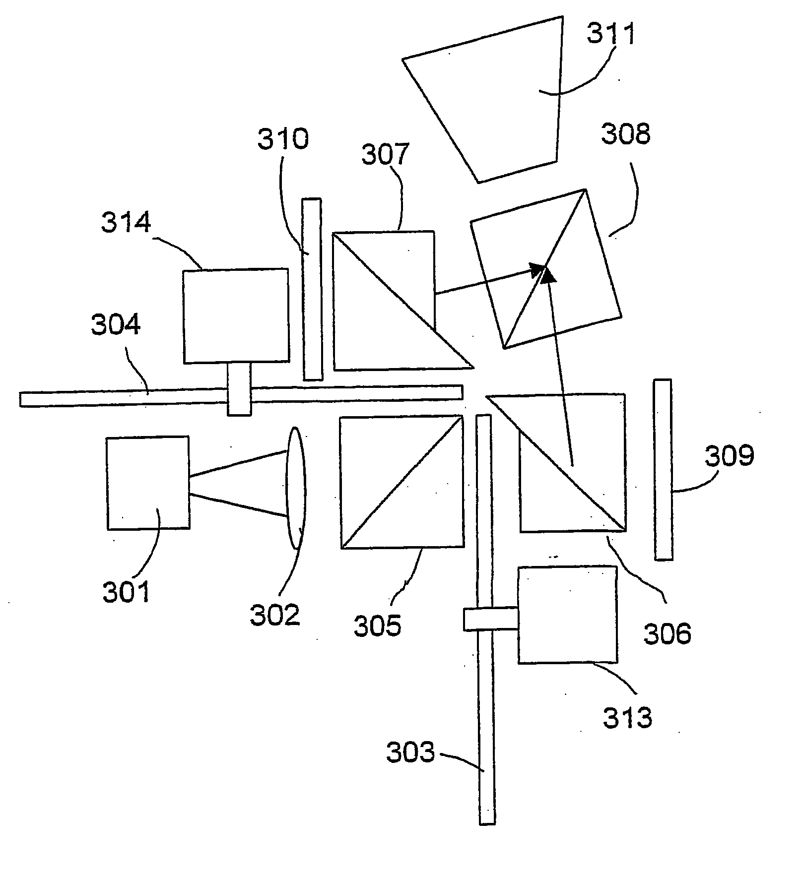
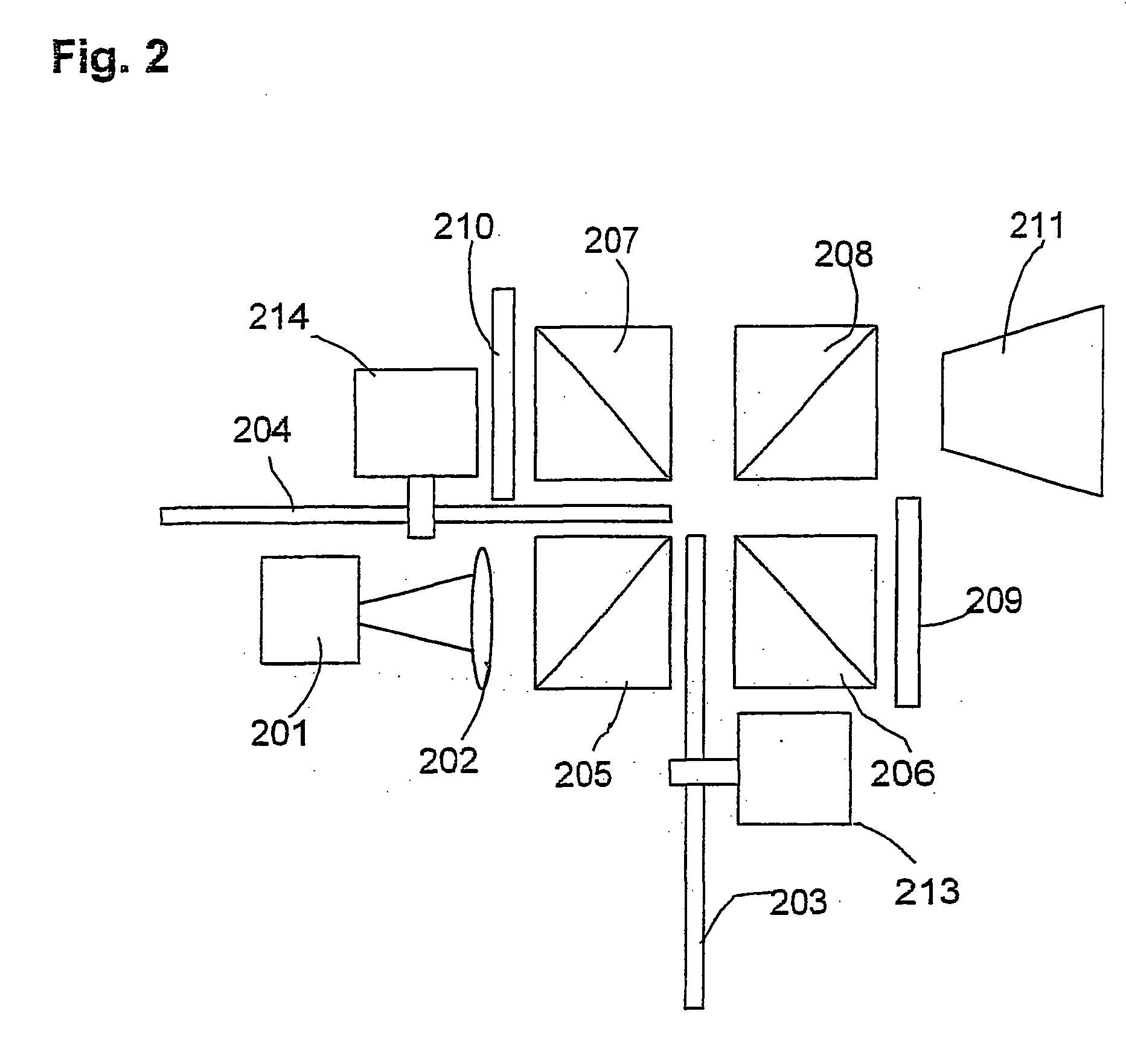
[0037] Reference is now made to FIG. 2, which schematically illustrates a cross-sectional top view of an optical engine configuration for a more-than-three-primaries color projection display system, using two LCoS SLM panels, in accordance with an embodiment of the invention In this embodiment, non-polarized light from an illumination unit 201, which may include at least one white light source, for example, the UHP™ lamp available from Philips Lighting, a cold filter, and a homogenizing component...


PUM

PropertyMeasurementUnit
angleaaaaaaaaaa
off-normal angleaaaaaaaaaa
wavelength spectrumsaaaaaaaaaa

Abstract

A color projection display device may include SLMs or other panels. One embodiment includes a device for displaying a color image including first and second sequences of temporally-integrateable primary color image components, the device also includes first (209) ans second (206) SLM panels (604, 606), first and second driving circuitry, and first through fourth polarizing beam splitters.

Description

FIELD OF THE INVENTION [0001] The Invention relates to color display devices generally and, more particularly, to optical configurations of sequential projection color display devices using multiple imaging panels. BACKGROUND OF THE INVENTION [0002] Standard computer monitors and TV displays are typically based on three additive primaries; namely, red, green, and blue, collectively denoted RGB. These monitors may not be able to display many colors perceived by humans, since they are limited in the range of colors they are capable of displaying. [0003] Existing display devices can be divided into two groups, namely, direct view devices and projection devices. The direct view devices include CRT, LCD, LED and other types of display. In direct view devices, a display screen is composed of a plurality of, for example, RGB pixels, each pixel including a red sub-pixel element, a green sub-pixel element and a blue sub pixel element The color image is created by the viewer's visual system, ...

Claims


Application Information

Patent Timeline
Patent Type & Authority Applications(United States)
IPC IPC(8): G02F1/135G03B21/14G03B21/20G03B21/26G03B21/28H04N9/31H04N13/04H04N15/00
CPCH04N9/3114H04N9/3197H04N9/312H04N9/3117
Inventor ROTH, SHMUEL
Owner SAMSUNG DISPLAY CO LTD
Why Eureka
Try Eureka