[0015] A process gas can be used when
cutting by means of laser radiation, such that, by rapid
elimination of the melt in the area of the joint, a
cooling effect takes place which, depending on the cut material, can lead to an improvement in the quality of the cut edge. At the same time, an inflowing process gas can protect the
laser optics (focussing lens) and ensure less thermal loading of the environment. Typical process gases are air, N2, Ar or mixtures thereof.
[0016] In exemplary embodiments, the laser radiation used for cutting the analysis element or a constituent part of the analysis element has a laser power which is effective for this cutting and which is varied as a function of the thicknesses and materials of the material layers to be cut in the different areas. This has the
advantage that the cutting depth in each area of the analysis element blank can be controlled. The present invention thus provides a method for contactless separation (without mechanical influences such as knives or
ultrasound), by which analysis elements or analysis element constituents can be cut with a defined cutting depth from multi-layer analysis element blanks, which can consist for example of a support film,
adhesive layers, an
enzyme-containing detection layer and a fabric. Depending on the substrate, it is possible, by adjusting the power while maintaining a constant focus position, to introduce an optimal energy per unit length (J / m) into the material to be cut. In addition to this, the energy introduced can be controlled by changing the focus position.
[0017] In the case of materials composed of fibres (for example
polymer fabrics), fraying can advantageously be avoided by cutting by means of laser radiation.
Adhesive-containing layers can be cut by means of laser without any
contamination of the cutting instrument. No undesired particles or dust are formed during cutting.
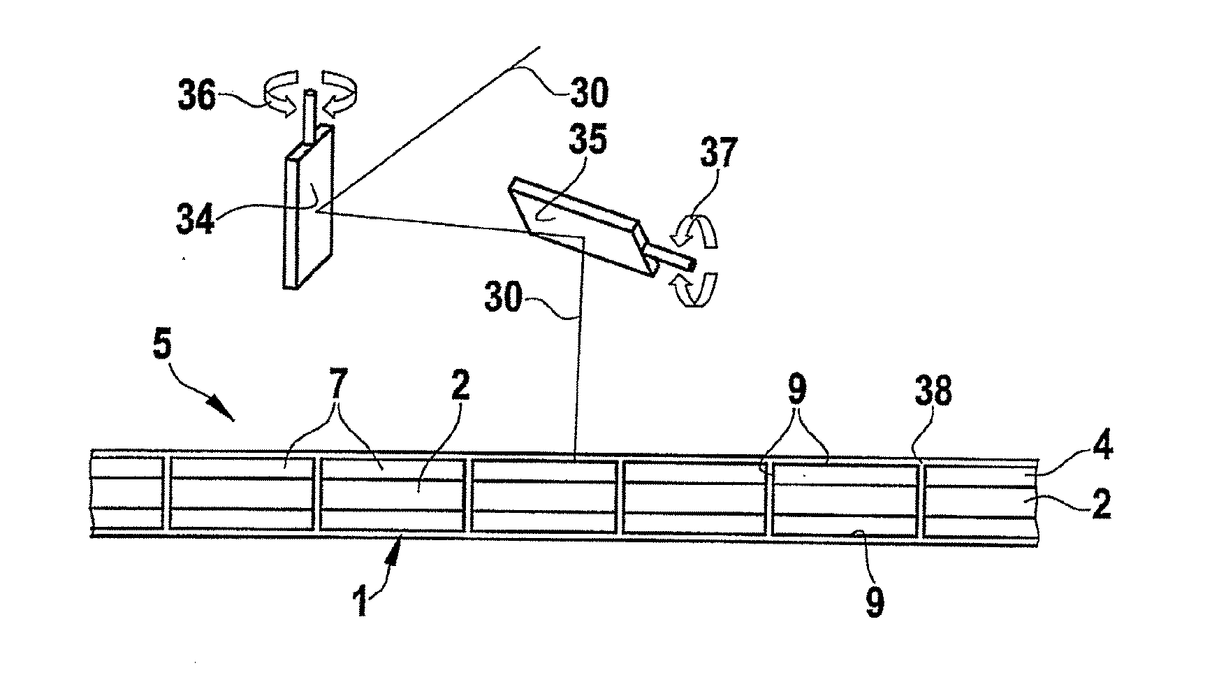
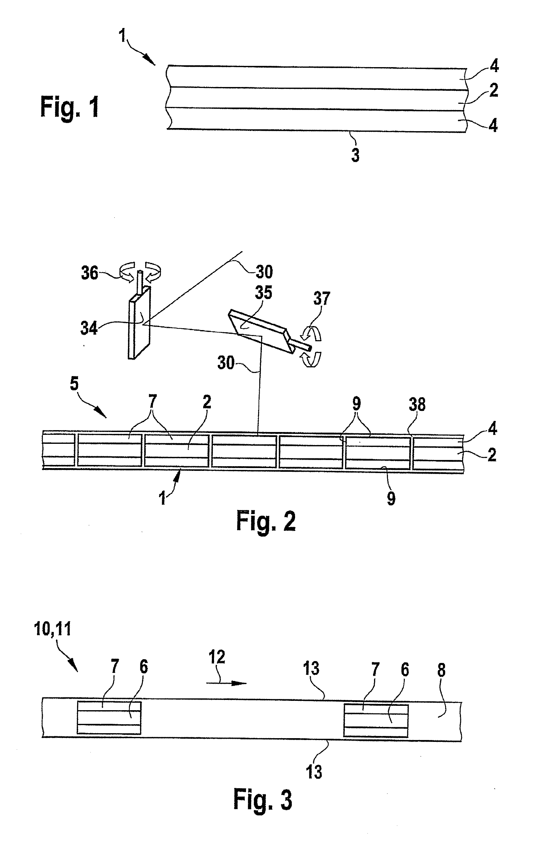
[0018] The cutting by means of laser radiation also affords the
advantage of increased flexibility in the formation of a cutting contour. For contour cutting, a laser beam emerging from a laser is successively directed at two mirrors that can be tilted in the x direction and y direction and from there is focussed on the analysis element that is to be cut. The two mirrors are automatically tilted by scanners (for example electronic drives), such that the focussed laser beam travels along the desired contour on the analysis element blank at a defined speed. The analysis element blank is able to move relative to the mirrors or can remain stationary until the respective contour has been created. The scanners of the mirrors can be controlled by a control appliance.
[0031] A hydrophobic layer prevents spreading of an aqueous sample. It can, for example, surround a test field in such a way that a liquid sample is “trapped” in the test field. The hydrophobic layer can be produced, for example, by impregnation of defined areas of other layers of the analysis element blank.
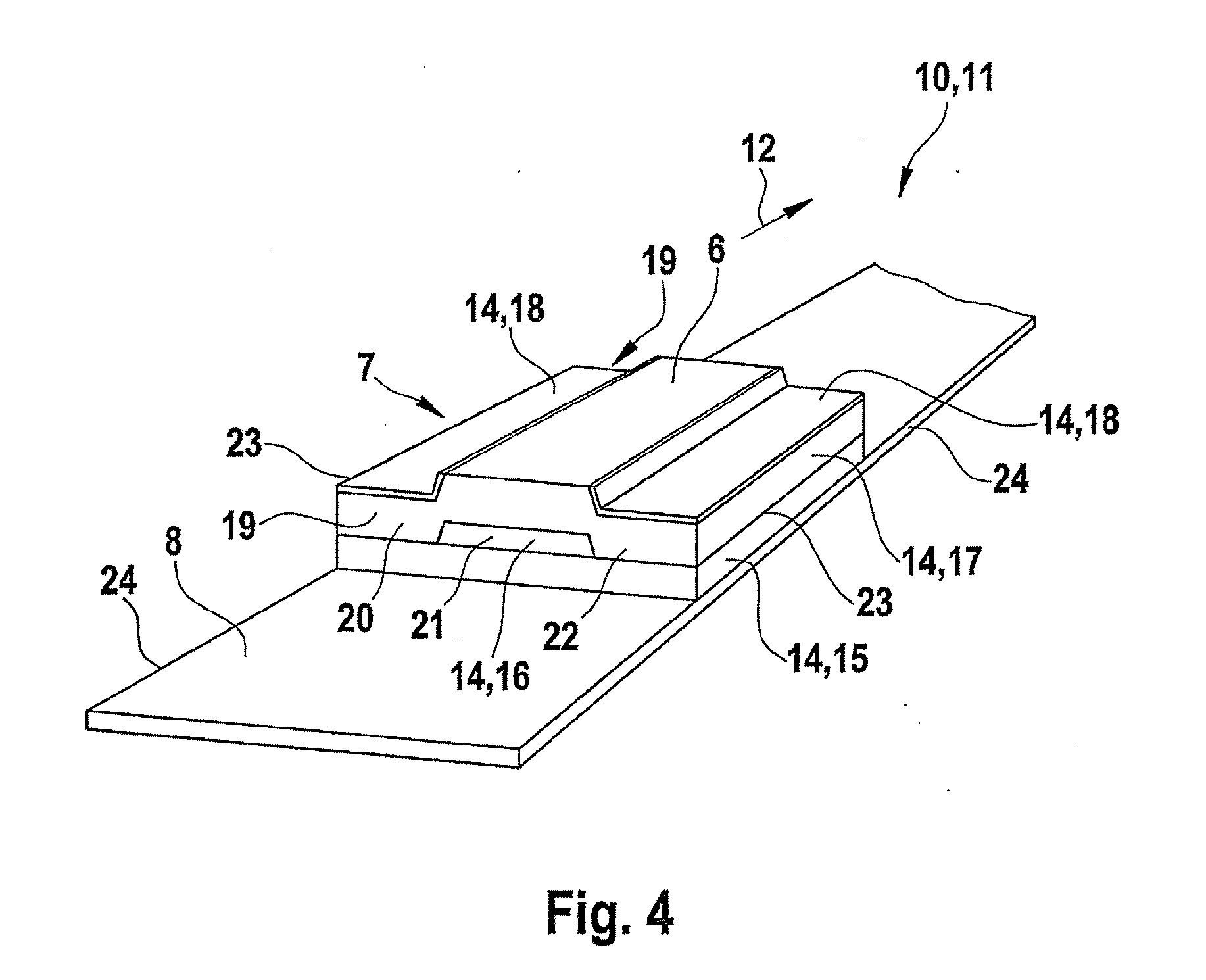
[0035] A layer that can be melted by the laser radiation is, for example, a
thermoplastic polymer layer that is melted by the laser radiation in the area of the cut edge that is formed. According to an exemplary embodiment, during the cutting of the multi-layer analysis element or of the constituent part of the multi-layer analysis element by means of laser radiation from the analysis element blank along at least one cut edge, at least one material layer is melted by the laser radiation, such that it has a
rounding effect on the cut edge. This has the
advantage that the rounded cut edge does not cause any injuries or damage, for example, if it is moved along the
skin of a patient or along a seal in the analysis appliance.

