Imaging lens

a technology of imaging lens and peripheral area, applied in the field of imaging lens, can solve the problems of inability to obtain excellent optical performance and difficulty in correcting aberrations at a peripheral area, and achieve the effect of low profile, correcting aberrations, and high resolution

Active Publication Date: 2021-11-09
TOKYO VISIONARY OPTICS CO LTD
View PDF2 Cites 2 Cited by
  • Summary
  • Abstract
  • Description
  • Claims
  • Application Information

AI Technical Summary

Benefits of technology

[0165]According to the present invention, there can be provided an imaging lens with high resolution which satisfies demand of the wide field of view, the low profile and the low F-number in well balance, and properly corrects aberrations.

Problems solved by technology

However, in lens configurations disclosed in the Patent Document 1, when wide field of view, low profile, and low F-number are to be realized, it is very difficult to correct aberrations at a peripheral area, and excellent optical performance can not be obtained.

Method used


Image

  • Imaging lens
  • Imaging lens
  • Imaging lens

Examples


example 1

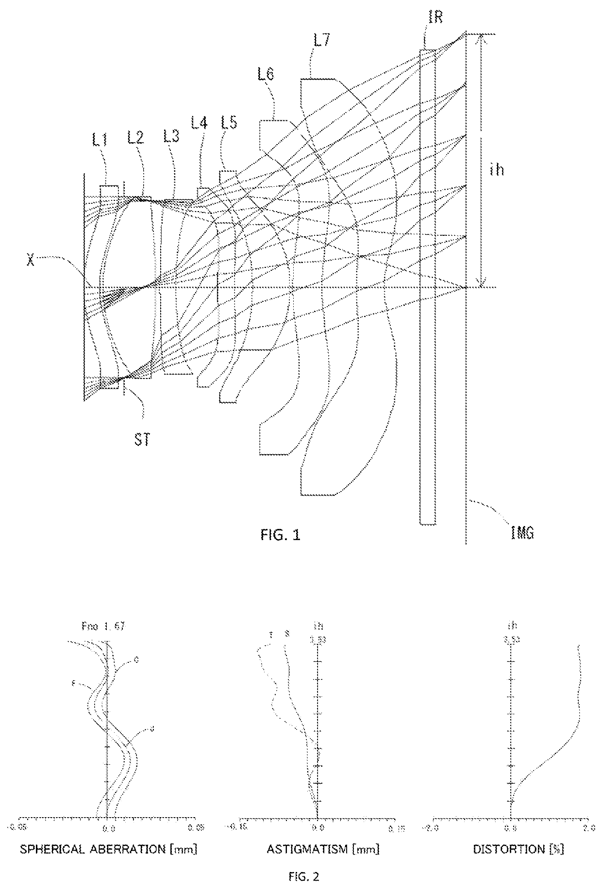
[0247]The basic lens data is shown below in Table 1.

[0248]

TABLE 1Example 1Unit mmf = 4.20Fno = 1.67ω(°) = 39.5ih = 3.53TTL = 5.23Surface DatairdNdvd(Object)InfinityInfinity 1*1.84420.22001.65021.54(vd1) 2*1.44560.34433 (Stop)Infinity−0.3000 4*1.69170.72931.54455.57(vd2) 5*−24.98770.0630 6*7.75600.22001.67119.24(vd3) 7*4.15260.5819 8*6.00810.23001.67119.24(vd4) 9*5.48950.253310*−2.56340.52251.54455.57(vd5)11*−1.63320.034612*3.52200.40691.65021.54(vd6)13*3.81380.473414*2.98220.39031.54455.57(vd7)15*1.34320.500016Infinity0.21001.51764.2017Infinity0.4235Image PlaneConstituent Lens DataLensStart SurfaceFocal LengthComposite Focal LengthSag at Peripheral Area of Effective Diameter11−13.146f1235.148Sag2F0.438242.942Entrance Pupil DiameterSag3R0.23336−13.661EPD2.518Sag4F−0.28248−115.367Back Focus5106.909Bf1.06261245.674714−4.906Aspheric Surface DataFirst SurfaceSecond SurfaceFourth SurfaceFifth SurfaceSixth SurfaceSeventh SurfaceEighth Surfacek−1.512462E+00−2.696217E+00−2.048987E+00−4.62403...

example 2

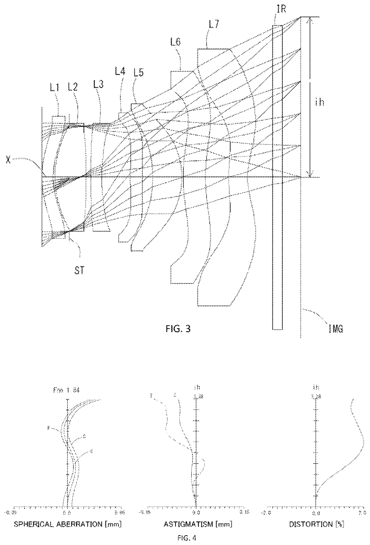
[0253]The imaging lens in Example 2 satisfies conditional expressions (2) to (8), and (10) to (26) as shown in Table 8.

[0254]FIG. 4 shows spherical aberration (mm), astigmatism (mm), and distortion (%) of the imaging lens in Example 2. As shown in FIG. 4, each aberration is corrected excellently.

Example 3

[0255]The basic lens data is shown below in Table 3.

[0256]

TABLE 3Example 3Unit mmf = 4.25Fno = 1.48ω(°) = 37.2ih = 3.28TTL = 5.20Surface DatairdNdvd(Object)InfinityInfinity 1*1.82600.24001.65021.54(vd1) 2*1.50530.33603 (Stop)Infinity−0.3000 4*1.74130.85961.54455.57(vd2) 5*59.79490.0565 6*6.92090.24001.67119.24(vd3) 7*4.22500.2500 8Infinity0.2650 9*4.60220.24001.67119.24(vd4)10*4.78260.234211*−2.55820.50061.54455.57(vd5)12*−1.73680.021513*2.92800.39041.65021.54(vd6)14*3.11590.644115*9.31640.36561.58430.10(vd7)16*2.01140.500017Infinity0.21001.51764.2018Infinity0.2183Image PlaneConstituent Lens DataLensStart SurfaceFocal LengthComposite Focal LengthSag at Peripheral Area of Effective D...

example 3

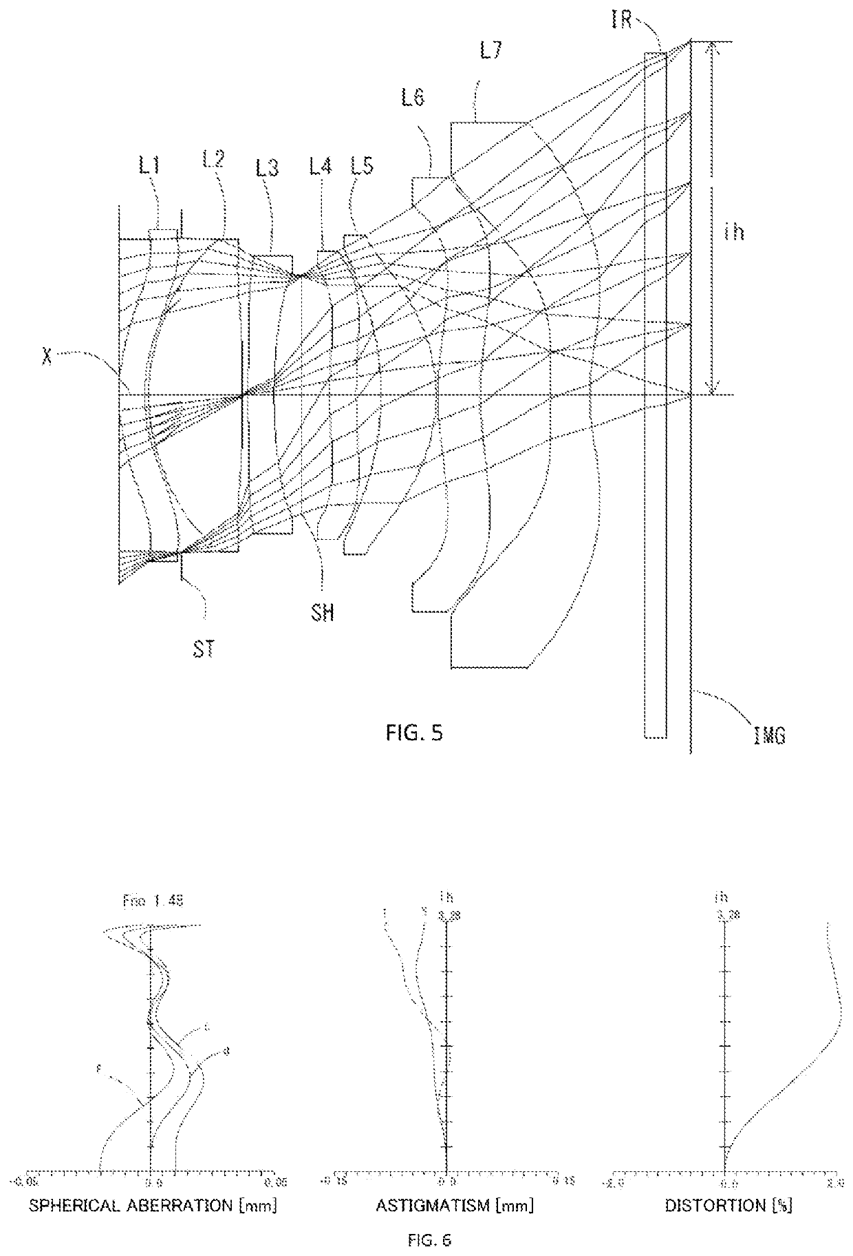
[0257]The imaging lens in Example 3 satisfies conditional expressions (2) to (8), and (10) to (26) as shown in Table 8.

[0258]FIG. 6 shows spherical aberration (mm), astigmatism (mm), and distortion (%) of the imaging lens in Example 3. As shown in FIG. 6, each aberration is corrected excellently.

Example 4

[0259]The basic lens data is shown below in Table 4.

[0260]

TABLE 4Example 4Unit mmf = 4.25Fno = 1.47ω(°) = 39.1ih = 3.53TTL = 5.17Surface DatairdNdvd(Object)InfinityInfinity 1*1.73220.24001.65021.54(vd1) 2*1.42480.38503 (Stop)Infinity−0.3500 4*1.74480.86011.54455.57(vd2) 5*49.15860.0552 6*6.70590.24001.67119.24(vd3) 7*4.28490.2600 8Infinity0.3115 9*5.65250.24001.67119.24(vd4)10*5.83210.227611*−2.57000.44061.54455.57(vd5)12*−1.70070.024913*3.04950.36981.65021.54(vd6)14*3.46390.641815*13.06840.35161.54455.57 (vd7)16*1.93920.500017Infinity0.21001.51764.2018Infinity0.2333Image PlaneConstituent Lens DataLensStart SurfaceFocal LengthComposite Focal LengthSag at Peripheral Area of Effective...


PUM


Abstract

There is provided an imaging lens with excellent optical characteristics which satisfies demand of wide field of view, low profile and low F-number. An imaging lens comprises, in order from an object side to an image side, a first lens, an aperture stop, a second lens with positive refractive power in a paraxial region, a third lens with negative refractive power in the paraxial region, a fourth lens, a fifth lens with the positive refractive power in the paraxial region, a sixth lens being a double-sided aspheric lens, and a seventh lens with negative refractive power having an image-side surface being concave in the paraxial region and an aspheric surface having at least one pole point in a position off the optical axis.

Description

[0001]The present application is based on and claims priority of a Japanese patent application No. 2018-195773 filed on Oct. 17, 2018, the entire contents of which are hereby incorporated by reference.BACKGROUND OF THE INVENTIONField of the Invention[0002]The present invention relates to an imaging lens which forms an image of an object on a solid-state image sensor such as a CCD sensor or a C-MOS sensor used in an imaging device.Description of the Related Art[0003]In recent years, it becomes common that camera function is mounted in various products, such as information terminal equipment, home appliances, automobiles, and the like. Development of products with the camera function will be made accordingly.[0004]The imaging lens mounted in such equipment is required to be compact and to have high-resolution performance.[0005]As a conventional imaging lens aiming high performance, for example, the imaging lens disclosed in Patent Document 1 below has been known.[0006]Patent Document ...

Claims


Application Information

Patent Timeline
Patent Type & Authority Patents(United States)
IPC IPC(8): G02B13/00G02B9/64
CPCG02B13/0045G02B9/64G02B13/18G02B13/06G03B30/00
Inventor FUKAYA, HISAO
Owner TOKYO VISIONARY OPTICS CO LTD
Why Eureka
Try Eureka