Vented nose trimmer

a nose trimmer and nose technology, applied in the direction of metal working devices, etc., can solve the problems of pain and possible injury in users, inefficient and limited cutting surfaces, and increased user injury probability

Active Publication Date: 2022-01-04
WILSON MELVIN
View PDF5 Cites 1 Cited by
  • Summary
  • Abstract
  • Description
  • Claims
  • Application Information

AI Technical Summary

Benefits of technology

[0007]In general, the nasal hair trimmer is configured for being operated within a nasal cavity for trimming nasal hair...

Problems solved by technology

Both the aforementioned types have difficulties in trimming typical nose hair in that they are very inefficient and provide limited cutting surfaces.
In some cases, the scissor action causes ripping, tearing or pinching o...

Method used


Image

  • Vented nose trimmer
  • Vented nose trimmer
  • Vented nose trimmer

Examples


Embodiment Construction

[0013]Certain terminology will be used in the following description for convenience in reference only and will not be limiting. For example, top, bottom, front, back, right and left refer to the illustrated embodiment as oriented in the view being referred to. The words “upwardly” and “downwardly” refer to directions up or down and away from, respectively, the geometric center of the embodiment being described and designated parts thereof. Such terminology will include the words specifically mentioned, derivatives thereof and words of similar meaning.

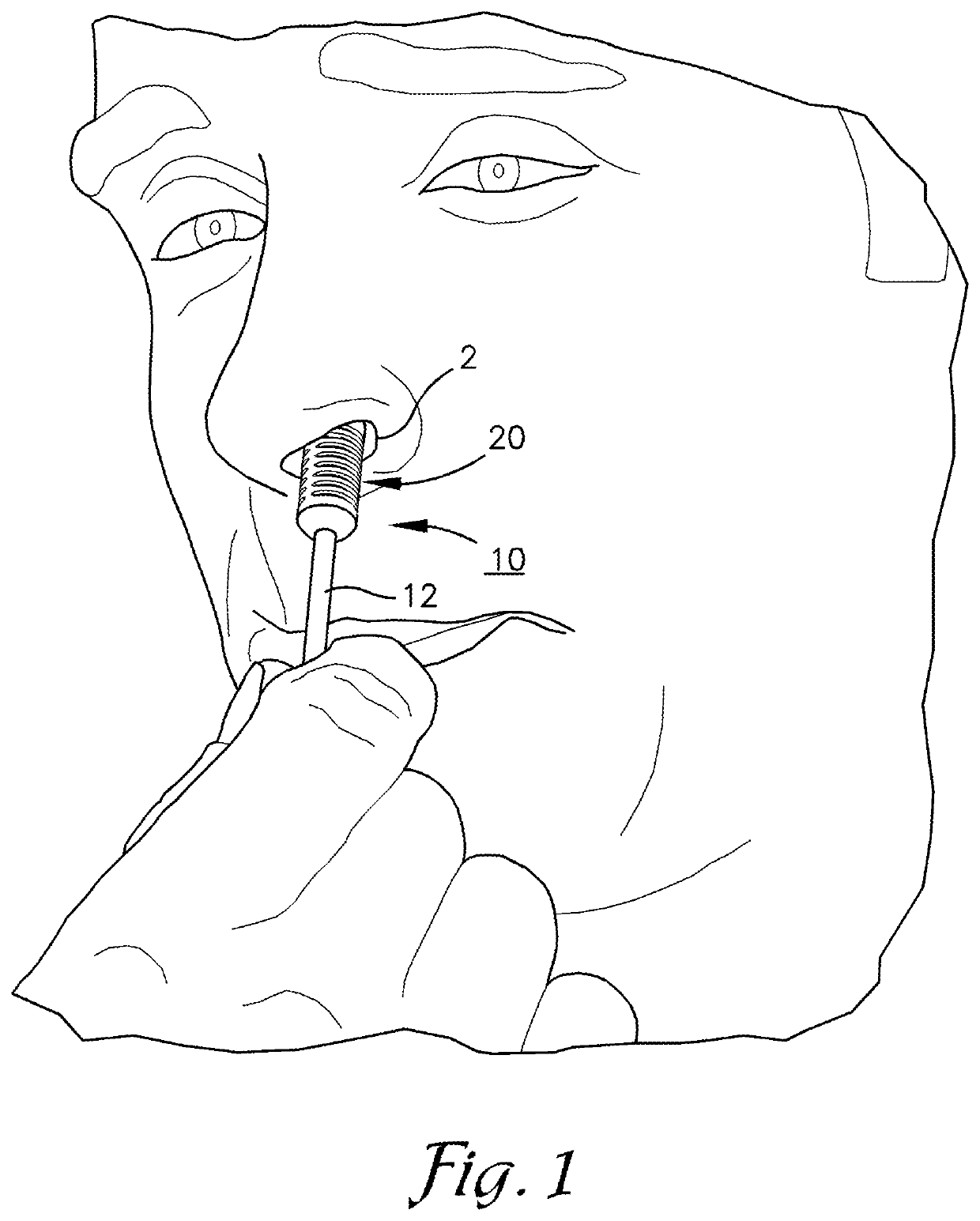
[0014]Referring to FIG. 1, an improved nose trimmer generally referred to by reference numeral 10 is illustrated as being received by an exemplary nasal cavity 2 associated with a user. The improved nose trimmer 10 generally includes an elongated handle 12 extending to a vented head assembly 20 which as depicted, is configured for receipt within a typical nasal cavity.

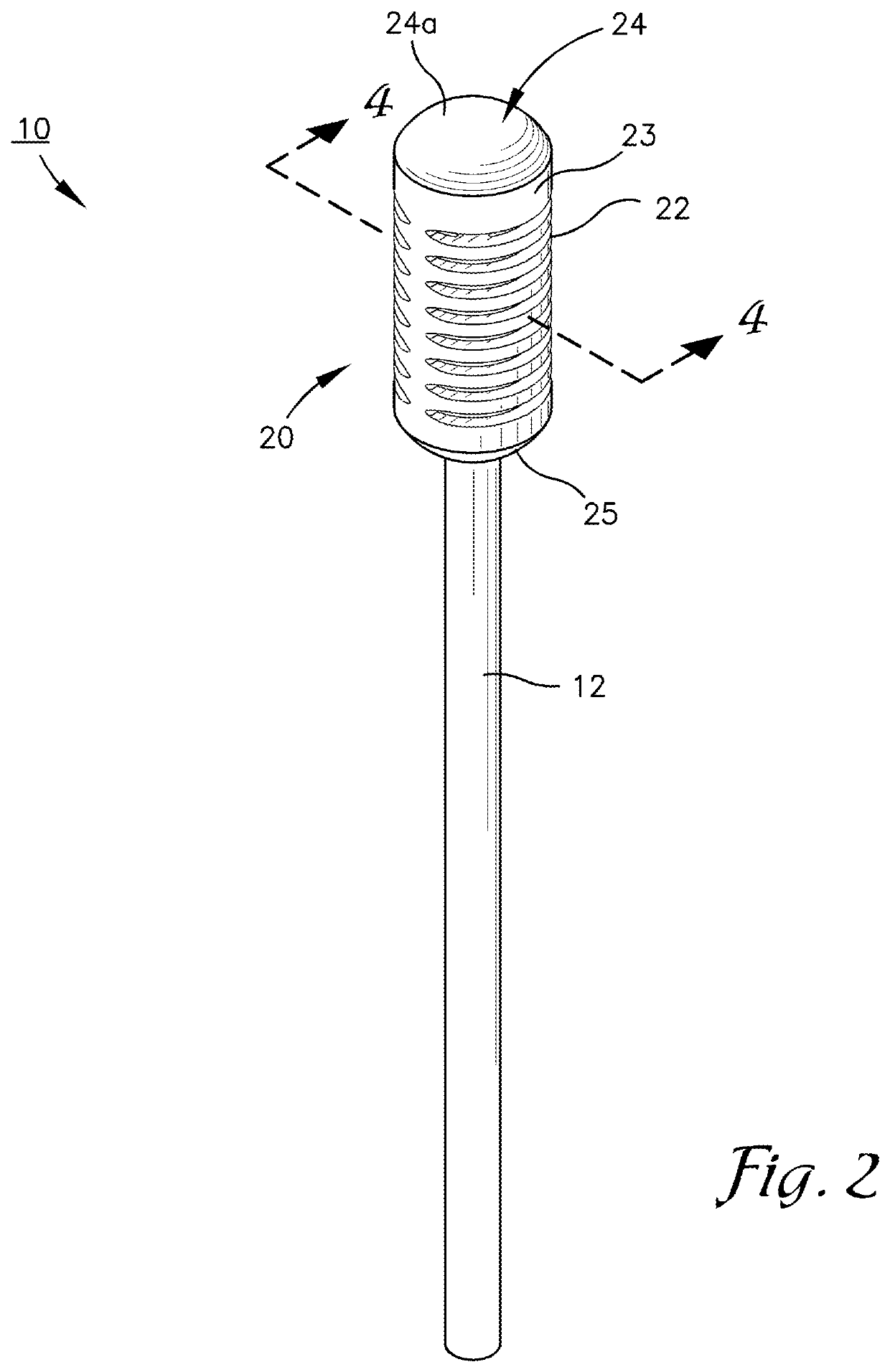
[0015]As further depicted in FIG. 2, the embodiment of the improved n...


PUM


Abstract

The present invention provides a reciprocally rotatable trimmer with a plurality of vents for removing nasal hair follicles, the vented nose trimmer including a head assembly and an elongated handle, the head assembly including a plurality of vents spaced along the head assembly for selectively trimming said nasal hair follicles.

Description

FIELD OF THE INVENTION[0001]The current invention relates in general to a nose hair trimmer and more specifically to a vented nose hair trimmer with a plurality of knives.BACKGROUND OF THE INVENTION[0002]Generally, there are two types of nose hair trimmers. Rotary nose hair trimmers and linear nose hair trimmers. A rotary nose hair trimmer uses a set of internally positioned rotary blades surrounded by a head housing the rotary blades for trimming nose hair. The head protects the nose from injury by maintaining the blades internally. A linear nose hair trimmer has movable blades, moving cooperatively with respect to a fixed blade, the blades being disposed in a head shaped for insertion into a nasal canal. Both the aforementioned types have difficulties in trimming typical nose hair in that they are very inefficient and provide limited cutting surfaces.[0003]Typical nose trimmers use an arrangement of blades which includes two opposing blades where at least part of each of cutting s...

Claims


Application Information

Patent Timeline
IPC IPC(8): B26B19/14B26B19/30
CPCB26B19/148B26B19/30
Inventor WILSON, MELVIN
Owner WILSON MELVIN
Why Eureka
Try Eureka