Nasal dilator comprising joined legs with end pads and air passages

a dilator and end pad technology, applied in the field of intranasal instruments, can solve the problems of affecting the normal breathing of the skin, requiring installation, and being neither inexpensive nor disposable, and unable to meet the needs of patients,

Active Publication Date: 2014-09-16
INT PATENT DEV GROUP
View PDF10 Cites 64 Cited by
  • Summary
  • Abstract
  • Description
  • Claims
  • Application Information

AI Technical Summary

Problems solved by technology

While the foregoing arrangements are useful, they are bulky and require installation by knowledgeable technicians.
In addition, they are neither inexpensive nor disposable.
They also block normal breathing of the skin and may lose their adhesive tack as the user perspires.
Ruiz asserts that the device may be wearable during sports activities, but since it resides partially outside the wearer's nose, it may easily become dislodged in some activities.
Since this device requires surgical implantation, it cannot be simply inserted by an untrained user.
Those devices that have no other restraining means and engage neither the septum nor the columella are at risk of being dislodged during use, for example during a vigorous sneeze.
From the above it is evident that although they may ease breathing to a degree, the prior-art devices suffer from various deficiencies.

Method used


Image

  • Nasal dilator comprising joined legs with end pads and air passages
  • Nasal dilator comprising joined legs with end pads and air passages
  • Nasal dilator comprising joined legs with end pads and air passages

Examples


first embodiment

Operation—FIG. 6

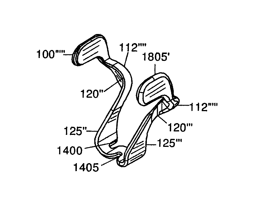
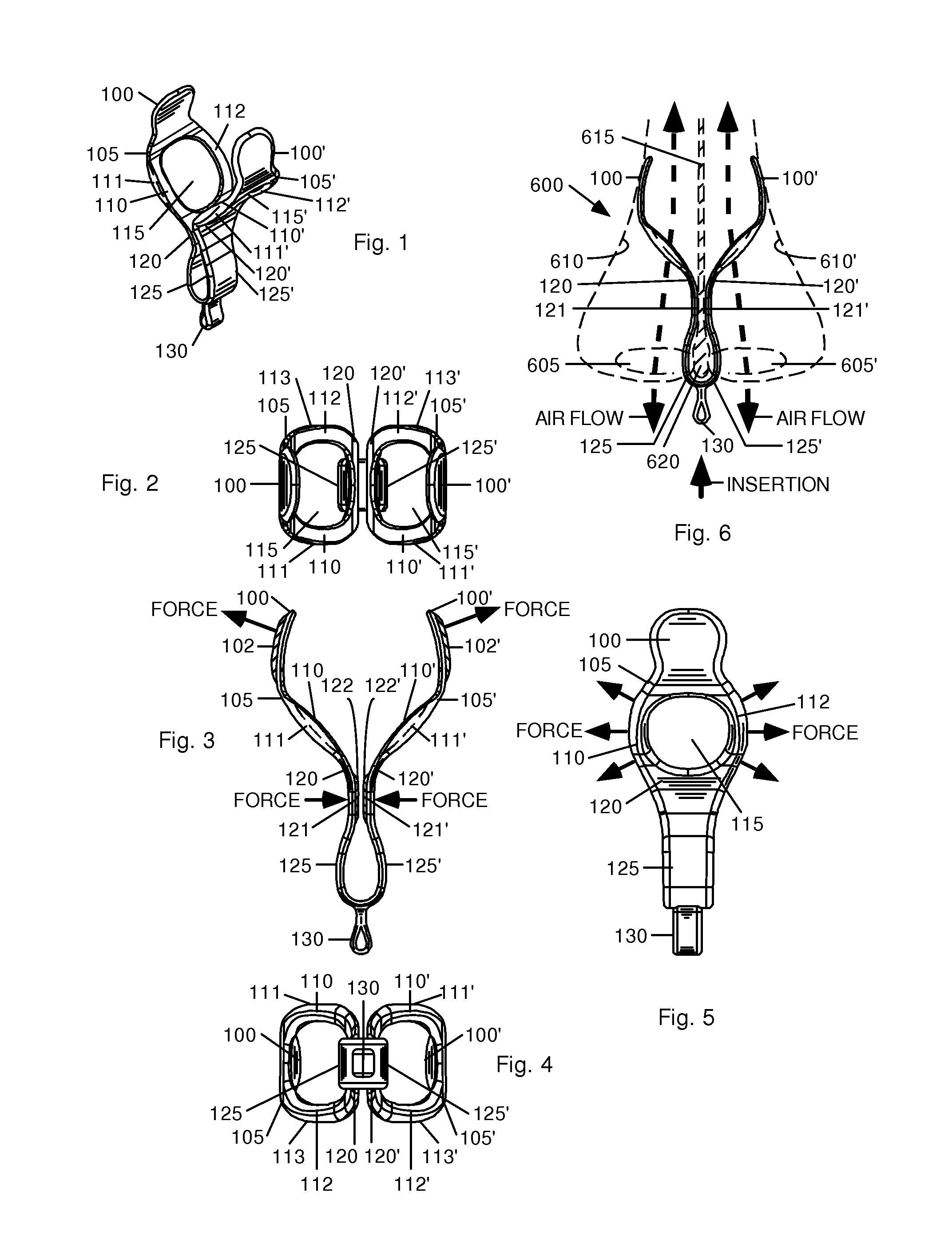
[0064]FIG. 6 shows a frontal view of the dilator fully inserted and in use in a wearer's nose. The nasal structures affected by insertion of the dilator include the nostrils 605 and 605′, the outer nostril walls 610 and 610′, the septum 615, and the columella (the fleshy, lower widened column at the base of the nasal septum, i.e., the portion of the septum that one sees when looking at a person's nose from the outside) 620. To use the dilator, the wearer grips handle 130, or the bight at the bottom of the dilator if no handle 130 is used, inserts tabs 100 and 100′ into nostrils 605 and 605′, and gently urges the dilator inward until the inside of the bight—the junction of vertical sections 125 and 125′—rests against columella 620. At this point, pads 100 and 100′ springably press against outer nasal walls 610 and 610′, urging them outward, away from septum 615, thereby enlarging the airway path of the nostril and easing the wearer's breathing as air freely flows thro...

first alternative embodiment

Description—FIG. 3—Cushions Added to Surfaces in Contact with Nasal Tissues

[0068]FIG. 3 is a front elevation view of the dilator. In order to further protect the nasal linings, optional cushions 102 and 102′ can be added to pads 100 and 100′. Similarly, optional cushions 122 and 122′ can be added inside pads 121 and 121′ to protect septum 615. In addition, cushions can be applied to surfaces 111, 111′, 113, and 113′. These cushions can be made of silicone rubber, caoutchouc (rubber), soft plastic, plastic foam, or foam rubber or any other suitable material. The cushions can optionally contain medications (not shown) that will diffuse into the wearer's nasal walls 610 and 610′ by virtue of contact between the two.

Second Alternative Embodiment

Description—FIGS. 7A-7F and 8—Dilating Arms Slidably Mounted with Respect to Each Other

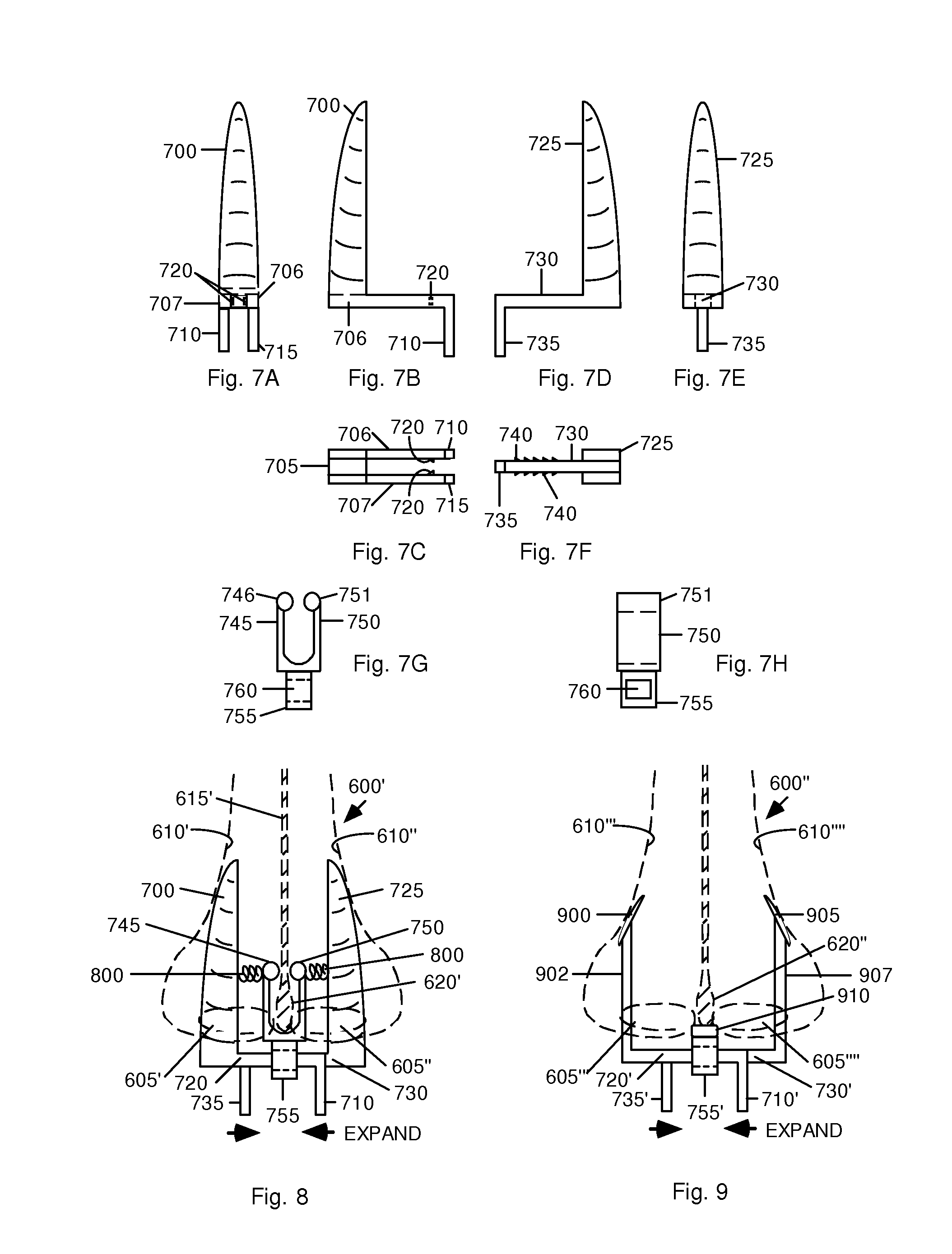
[0069]FIGS. 7A through 7H show another or second embodiment of a dilator comprising separate left and right portions which each have a center portion that exte...

second alternative embodiment

Operation—FIG. 8

[0073]FIG. 8 shows frontal view of a wearer's nose 600′ with nostrils 605′ and 605″, nasal walls 610′ and 610″, septum 615′, and columella 620′, and a dilator in place. Rails 720 and 730 have been inserted through opening 760 in portion 755.

[0074]The dilator of this embodiment is initially supplied with rail 730 inserted into the gap between rails 706 and 707 with vertical members 700 and 725 at rest as close as possible to each other. In this position, handles 710 and 735 are at their maximum separation.

[0075]To use the dilator, the wearer inserts members 700 and 725 into nostrils 605′ and 605″, respectively, until the bight portion of the dilator rests against columella 620′. Balls 746 and 751 at the ends of arms 745 and 750 may touch septum 615′ and will surround columella 620, ensuring that the dilator will not be unintentionally ejected from nose 600′. Then the user gently squeezes handles 710 and 735 together, forcing members 700 and 725 apart until the desired...


PUM


Abstract

One embodiment of a nasal dilator comprises a pair of pads (100), supported by arms (110, 112) surrounding an air passage (115). Each arm has a bend portion (120) and a pad (121) that grips a wearer's septum (615). Leg portions (125, 125′) extend down from the arms and are connected by a bight that surrounds the wearer's columella (620). The dilator is installed by gripping an optional handle (130) or the bight and inserting the pads and the arms into both nostrils. The dilator is urged upward and inward until the inner side of the bight touches the wearer's columella. To remove the dilator, the user grips the handle or bight and gently pulls downward until the dilator is removed. In an alternative embodiment, optional cushions (102, 122) soften the contact points between the dilator and the user's nasal structures and can supply medications through the user's nasal membranes.

Description

CROSS-REFERENCE TO RELATED APPLICATION[0001]This application is a division of application Ser. No. 12 / 332,310, filed 2008 Dec. 10, which is a continuation-in-part (CIP) of application Ser. No. 12 / 196,625, filed 2008 Aug. 22, which in turn is a CIP of application Ser. No. 11 / 954,961, filed 2007 Dec. 12.BACKGROUND[0002]1. Field[0003]The field is breathing aids, in particular intranasal instruments for dilating human nasal passages.[0004]2. Prior Art Nasal Dilators[0005]The following is a tabulation of some prior art (discussed below) that presently appears relevant:[0006]Pat. or Pub. Nr.Kind CodeIssue or Pub. DatePatentee or Applicant2,335,936B1Dec. 07, 1943Hanlon3,710,799B1Jan. 16,1973Caballero4,105,035B1Aug. 08, 1978Rella4,414,977B1Nov. 15, 1983Rezakhany5,479,944B1Jan. 02, 1996Petruson5,665,104B1Sep. 09, 1997Lee5,727,543B1Mar. 17, 1998Corsaro5,816,241B1Oct. 06, 1998Cook5,850,834B1Dec. 22, 1998Yoshida et al.5,895,409B1Apr. 20, 1999Mehdizadeh5,931,852B1Aug. 03, 1999Brennan5,931,854B1A...

Claims


Application Information

Patent Timeline
Patent Type & Authority Patents(United States)
IPC IPC(8): A61F5/08
CPCA61F5/08
Inventor BROWN, GREGORY A. M.BROWN, BRIAN A.
Owner INT PATENT DEV GROUP
Why Eureka
Try Eureka