

Wire electrical discharge machine and placement time calculation method
a technology of wire electrical discharge machine and placement time calculation, which is applied in the direction of electrical programme control, program control, instruments, etc., can solve the problems of flatness and parallelism wear of the upper soon deterioration of the flatness so as to suppress the deterioration of the accuracy of the top surface of the worktable
- Summary
- Abstract
- Description
- Claims
- Application Information
AI Technical Summary
Benefits of technology
Problems solved by technology
Method used
Image

Examples
first embodiment
[Overall Configuration of Wire Electrical Discharge Machine]
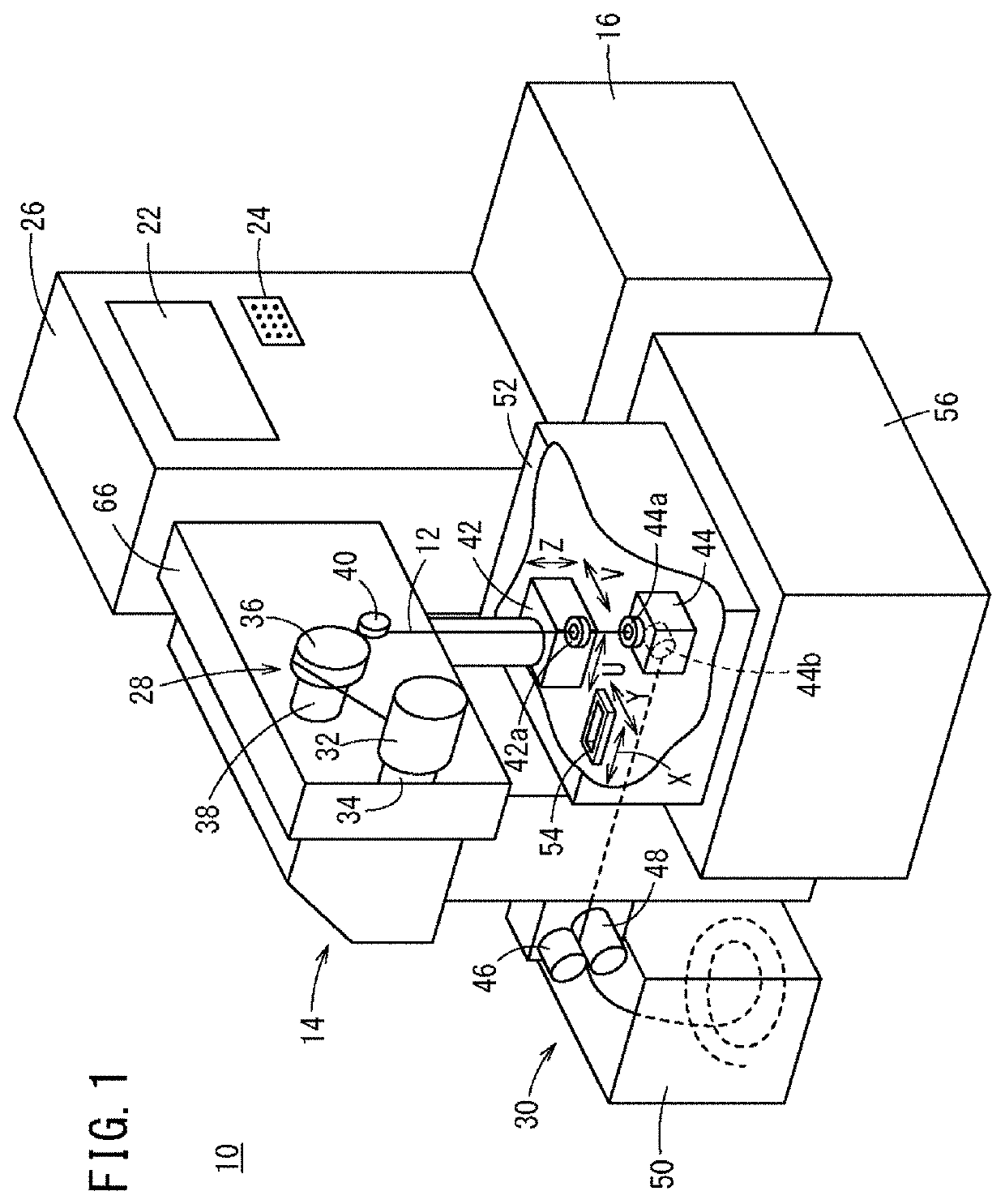
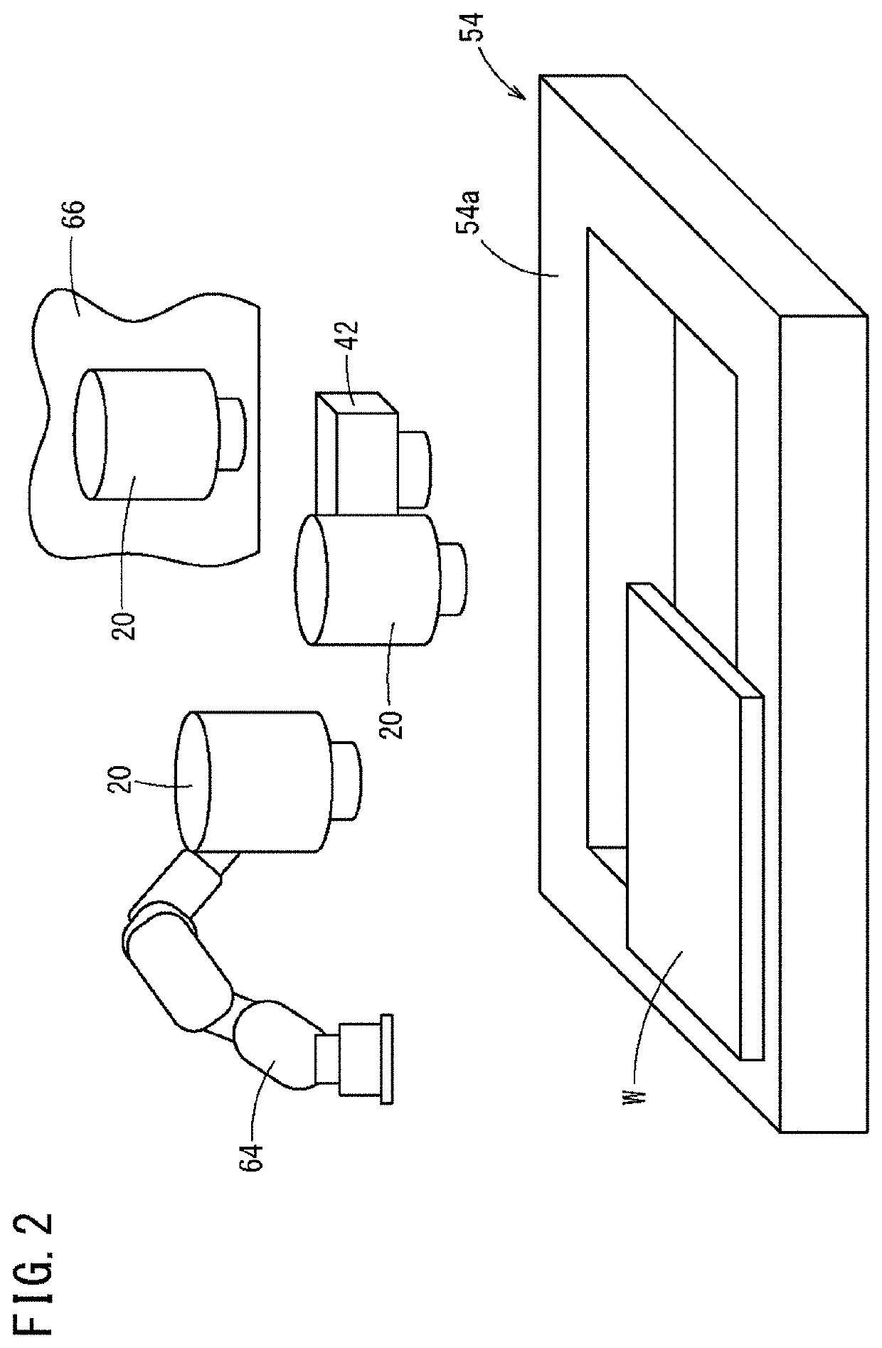
[0031]FIG. 1 is a mechanical schematic configuration diagram of the wire electrical discharge machine 10. FIG. 2 is a diagram illustrating an example of a position at which a camera 20 is attached to the wire electrical discharge machine 10.
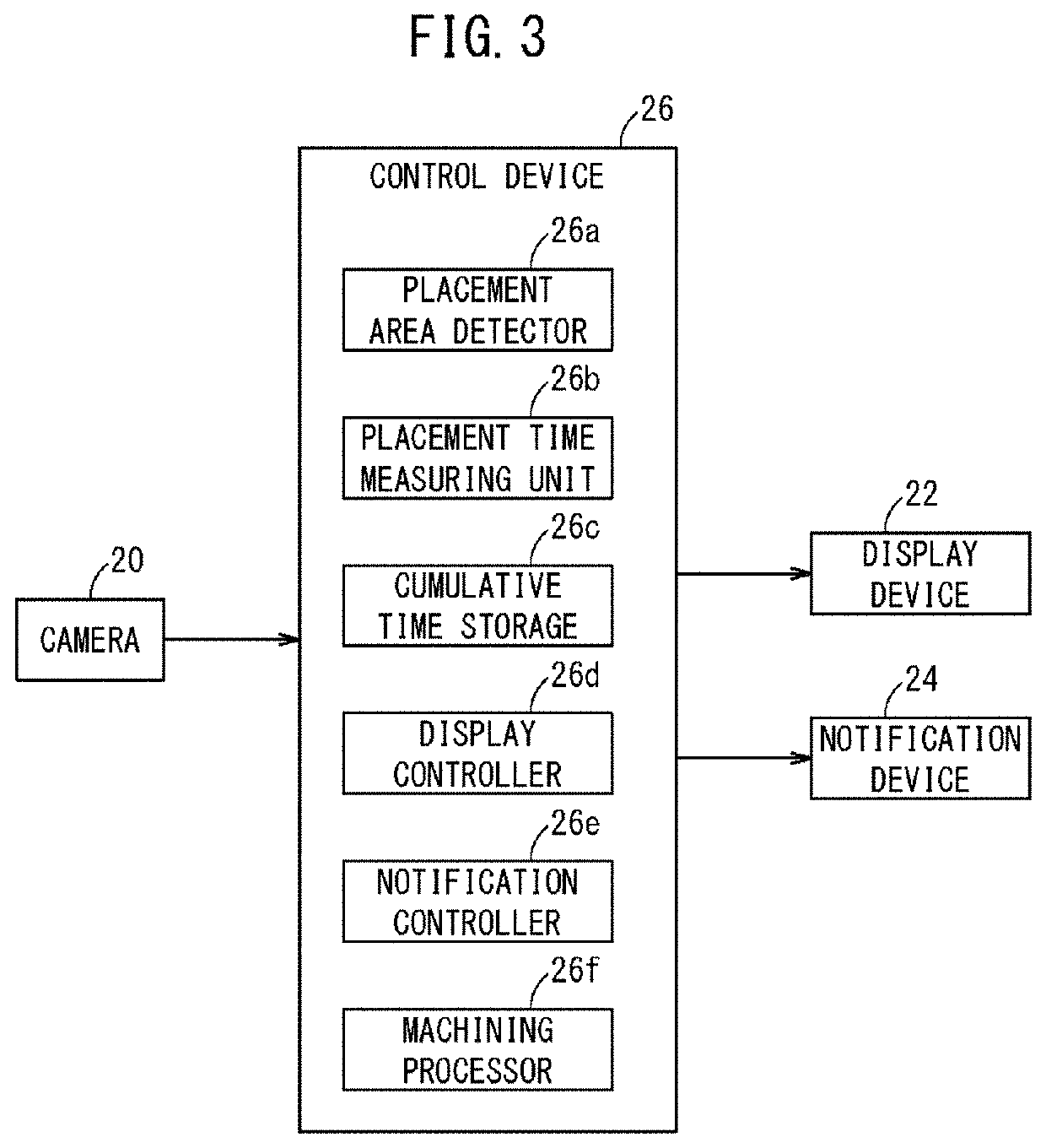
[0032]The wire electrical discharge machine 10 generates electric discharge by applying voltage across an electrode gap (clearance) formed between a wire electrode 12 and an object to be machined (workpiece) W in a working fluid, so as to perform machining (electrical discharge machining) on the workpiece W. The wire electrical discharge machine 10 includes a main machine body 14, a working fluid processor (dielectric fluid unit) 16, a camera (imaging unit) 20, a display device (display unit) 22, a notification device (notifying unit) 24, and a control device 26.
[0033]The wire electrode 12 is formed of, for example, metal material such as tungsten-based, copper-alloy based, and brass-bas...
second embodiment
[0078]In the first embodiment, the areas 58 in which the workpiece W is lying on the top surface 54a of the worktable 54 are determined from the image of the top surface 54a of the worktable 54 captured by the camera 20. On the other hand, in the second embodiment, a strain gauge (load sensor) 60 for detecting loads acting on the top surface 54a of the worktable 54 is provided so as to determine the areas 58 in which the workpiece W is lying on the top surface 54a of the worktable 54 based on the loads detected by the strain gauge 60. Though the second embodiment will be described hereinbelow, description of the same components as those in the first embodiment will be omitted by allotting the same reference numerals.
[0079]FIG. 7 is a view showing an example of a position where the strain gauge 60 is attached to the wire electrical discharge machine 10. The strain gauge 60 is provided on a lower portion of the worktable 54. The strain gauge 60 can detect whether or not a load acts on...
third embodiment
[0082]In the first embodiment, the areas 58 in which the workpiece W is lying on the top surface 54a of the worktable 54 are determined from the image of the top surface 54a of the worktable 54 captured by the camera 20. On the other hand, in the third embodiment, ammeters 62 for detecting the electric current flowing within the worktable 54 are arranged so as to determine the areas 58 in which the workpiece W is lying on the top surface 54a of the worktable 54 based on the electric current detected by the ammeters 62. Though the third embodiment will be described hereinbelow, description of the same components as those in the first embodiment will be omitted by allotting the same reference numerals.
[0083]FIG. 8 is a view illustrating a configuration in which ammeters 62 are arranged with respect to the wire electrical discharge machine 10. A plurality of ammeters 62 are provided on the worktable 54. While the workpiece W is processed by electrical discharge machining, the electric ...
PUM
| Property | Measurement | Unit |
|---|---|---|
| voltage | aaaaa | aaaaa |
| area | aaaaa | aaaaa |
| areas | aaaaa | aaaaa |
Abstract
Description
Claims
Application Information