Supercharge Your Innovation With Domain-Expert AI Agents!

Liquid crystal projector

a liquid crystal display and projector technology, applied in the field of lcd units, can solve the problems of increasing serious problems such as the life of lcd panels and polarization plates, and achieve the effect of reducing the cost of lcd projectors

Inactive Publication Date: 2012-02-07
SANYO ELECTRIC CO LTD
View PDF3 Cites 0 Cited by
  • Summary
  • Abstract
  • Description
  • Claims
  • Application Information

AI Technical Summary

Benefits of technology

The invention is an LCD projector with a highly transparent auxiliary polarization plate that improves the life of the associated polarization plate on the light emitting side of the LCD panel while reducing color irregularity and contrast degradation. The LCD projector includes LCD panels, a projection lens, and a source of light. Each LCD panel has a first and a second polarization panel, and a highly transparent auxiliary polarization panel is provided between the LCD panel and the second polarization panel. The highly transparent auxiliary substrate is supported by an optically anisotropic substrate with refractive index anisotropy, which helps to reduce variations in polarization status of light passing through the anisotropic transparent substrate. Cooling of the LCD panel is enhanced by the optically anisotropic transparent substrate, which has high thermal conductivity. The invention can be cost-effective as a quartz substrate can be used instead of a single-crystalline sapphire substrate.

Problems solved by technology

Decrease in life of an optical apparatus such as LCD panels and polarization plates has become increasingly a serious problem in recent years as they are used in LCD projector operated at high brightness and high contrast.
Unfortunately, however, inclination of C axis (or Z axis in the case of sapphire single crystal) of a highly transparent auxiliary polarization plate on the light emitting side has more influence on the display performance of the LCD panel than that of the aforementioned ordinary polarization plate.
For example, the inclination is often a source of color irregularity on a supposedly black screen and / or a source of contrast loss of a picture.

Method used


Image

  • Liquid crystal projector
  • Liquid crystal projector
  • Liquid crystal projector

Examples


Embodiment Construction

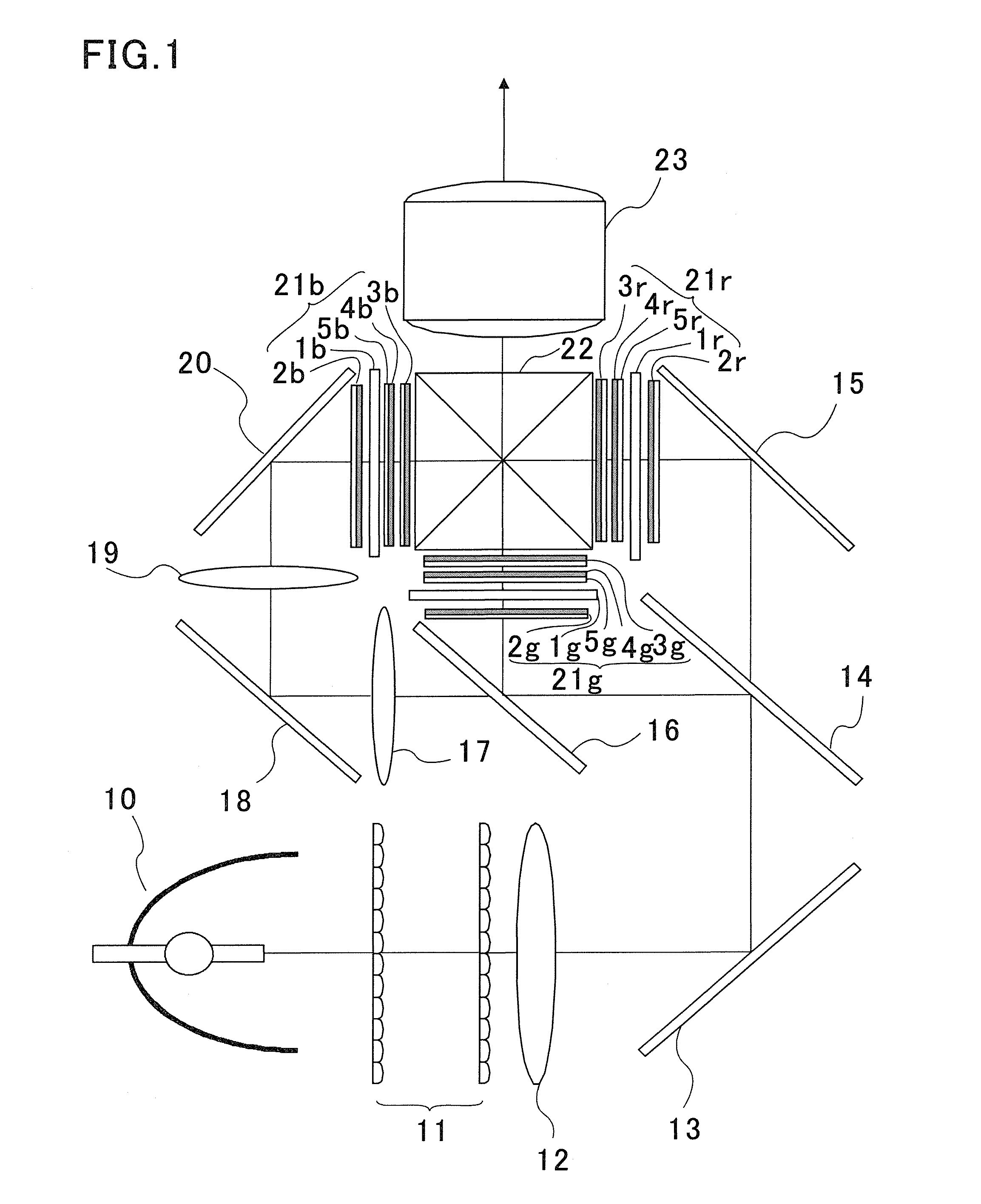
[0018]The invention will now be described in detail by way of example with referenced to the accompanying drawings. FIG. 1 is a plan view of an optical system for use with a three-plate type LCD projector in accordance with a first embodiment of the invention.

[0019]A beam of white light emitted from a light source 10 such as a metal halide lamp or an extra-high pressure mercury lamp passes through a pair of integrator lenses 11 and a condenser 12. The beam is then reflected by a total reflection mirror 13 through an angle of 90 degrees and led to the first dichroic mirror 14. Each of the integrator lenses 11 is designed to uniformize non-uniform luminous light emitted from the light source 10 to uniformly illuminate the entire surface of the LCD panel with light, thereby reducing the variations in the luminosity over the central and peripheral regions of the LCD panel.

[0020]The first dichroic mirror 14 transmits light in the red wavelength region, and reflects light in the cyanogen ...


PUM

PropertyMeasurementUnit
angleaaaaaaaaaa
inclination angleaaaaaaaaaa

Abstract

An LCD projector has LCD panels, each including polarization plates one on the light incidence side and another on the light emitting side of each LCD panel. The LCD panel is provided with a highly transparent auxiliary polarization plate between the LCD panel and the polarization plate on the light emitting side. The LCD panel is further provided with an optically anisotropic transparent substrate for supporting the highly transparent auxiliary polarization plate. The transparent substrate is arranged such that one of its anisotropic optical axes is inclined at an angle not more than 0.5 degrees with respect to the face of the auxiliary polarization plate when the face is parallel to the direction of light propagation. This arrangement ensures longer lives of the polarization plates on the light emitting sides while suppressing color irregularity on a black screen and degradation of picture contrast of the LCD projector.

Description

FIELD OF THE INVENTION[0001]This invention relates to a liquid crystal display (LCD), and more particularly, to an LCD unit.BACKGROUND OF THE INVENTION[0002]Decrease in life of an optical apparatus such as LCD panels and polarization plates has become increasingly a serious problem in recent years as they are used in LCD projector operated at high brightness and high contrast. To cope with this problem, each of the polarization plates is supported by a transparent substrate having an anisotropic refractive-index, such as a single-crystalline sapphire substrate or quartz substrate that has a good thermal conductivity (heat dissipation property).[0003]Japanese Patent Application Laid Open No. 2001-272671 discloses an LCD projector equipped with an optical system for providing illumination light, an electrooptic apparatus for modulating the light provided by the optical system based on picture information, and a projection system for projecting beams of light modulated by the electroop...

Claims


Application Information

Patent Timeline
Patent Type & Authority Patents(United States)
IPC IPC(8): G02F1/1335
CPCG03B21/00G03B21/006
Inventor UCHIYAMA, MASAHIROFURUTA, YOSHIHIRO
Owner SANYO ELECTRIC CO LTD
Features
  • R&D
  • Intellectual Property
  • Life Sciences
  • Materials
  • Tech Scout
  • Unparalleled Data Quality
  • Higher Quality Content
  • 60% Fewer Hallucinations
Learn More