Reinforcing bar coupler

a technology of reinforcing bars and couplers, which is applied in the direction of rod connections, building reinforcements, constructions, etc., can solve the problems of limited length of reinforcing bars, low resistance, cracked and destroyed, etc., and achieves the effect of reducing the manufacturing cost of rebar couplers, preventing rebar couplers from loosening, and facilitating maintenance and managemen

Active Publication Date: 2022-02-08
JEIL WIRE PRODN CO LTD +1
View PDF55 Cites 0 Cited by
  • Summary
  • Abstract
  • Description
  • Claims
  • Application Information

AI Technical Summary

Benefits of technology

[0031]The present invention has been made in view of the above-mentioned problems, and an object thereof is to provide a rebar coupler that can be prevented from loosening against tensile stress and compressive stress as well as impact or vibration.
[0032]It is another object of the present invention to provide a rebar coupler that includes a plurality of segments configured to have the same shape and size and generate a binding force by pressing an outer surface of a reinforcing bar, thereby achieving a reduction in manufacturing cost and facilitating maintenance and management.
[0033]It is still another object of the present invention to provide a rebar coupler that includes a spacer for allowing a plurality of segments to be radially spaced apart from each other, thereby enabling rebar connection to be more easily performed and working time to be significantly shortened.

Problems solved by technology

That is, since the concrete is significantly low in resistance to tensile stress (i.e., tensile strength), compared to resistance to pressure stress (i.e., pressure intensity), it is cracked and destroyed even due to a slight tensile stress.
Due to the enlargement and great height of reinforced concrete structures in recent years, the reinforcing bar inserted into concrete is relatively long, but the reinforcing bar is limitedly manufactured in length since it is a standard product fixed in length.
However, it is dangerous to apply the lap joint to a high-rise structure since it is low in durability, and the gas pressure welding joint is not safe since it causes cracks due to thermal deformation of heated portions.
Accordingly, the mechanical joint has been mainly used in recent years since it ensures durability, which is disadvantageous for the lap joint and the gas pressure welding joint, and is easy to construct.
However, the rebar coupler 1 having the above configuration has the following problems.
Meanwhile, since the conventional rebar joint disclosed in Korean Patent Nos. 1036594 and 0650376 also includes a large number of parts, the cost of the rebar joint is increased, it takes a long time to connect, and it is difficult to manage materials due to the loss and damage of parts and the like.
However, the related art illustrated in FIG. 4 has the following problems.
Hence, it is impossible to properly couple the reinforcing bars, and to satisfy compressive and tensile strength even though the reinforcing bars are coupled to each other.
In addition, when the fastening segments 20 and 21 are seated on the outer surfaces of the reinforcing bars 10 and 11, it is difficult to position the ends of the reinforcing bars 10 and 11 accommodated therein, which may lead to deterioration in assembling work.
Besides, since the fastening segments 20 and 21 are stored in a separated state, the maintenance and management thereof may be difficult.

Method used


Image

  • Reinforcing bar coupler
  • Reinforcing bar coupler
  • Reinforcing bar coupler

Examples


Embodiment Construction

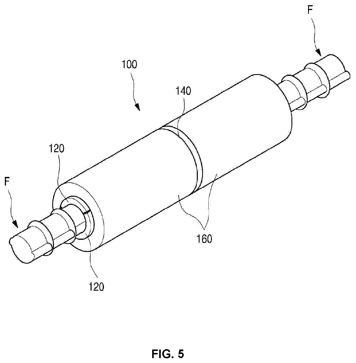
[0062]Hereinafter, a configuration of a rebar coupler 100 according to the present invention will be described in detail with reference to the accompanying drawings.

[0063]Prior to the description, it is noted that the terms and words used in the present specification and claims should not be construed as being limited to common or dictionary meanings but instead should be understood to have meanings and concepts in agreement with the spirit of the present invention based on the principle that an inventor can define the concept of each term suitably in order to describe his / her own invention in the best way possible.

[0064]Accordingly, since the embodiments described in the present specification and the configurations illustrated in the drawings are nothing but one preferred embodiment of the present invention and it does not cover all the technical ideas of the invention, it should be understood that various changes and modifications may be made at the time of filing the present appl...


PUM


Abstract

A rebar coupler that includes a plurality of segments having the same shape and radially arranged, the segments being seated on outer surfaces of a pair of reinforcing bars with ends of the reinforcing bars simultaneously accommodated therein, a spacer configured to accommodate the segments therein and support them while spacing the segments at regular intervals, and a pair of sleeves configured to press the outer surfaces of the reinforcing bars against inner peripheral surfaces of the segments by allowing the segments to be close to each other when the sleeves approach each other.

Description

REFERENCE TO RELATED APPLICATIONS[0001]This is a continuation of International Patent Application PCT / KR2018 / 002099 filed on Feb. 21, 2018, which designates the United States and claims priority of Korean Patent Application No. 10-2017-0073259 filed on Jun. 12, 2017 the entire contents of which are incorporated herein by reference.FIELD OF THE INVENTION[0002]The present invention relates to a rebar coupler that can be prevented from loosening against tensile stress and compressive stress as well as impact or vibration.[0003]The present invention relates to a rebar coupler that includes a plurality of segments configured to have the same shape and size and generate a binding force by pressing an outer surface of a reinforcing bar, thereby achieving a reduction in manufacturing cost and facilitating maintenance and management.[0004]The present invention relates to a rebar coupler that includes a spacer for allowing a plurality of segments to be radially spaced apart from each other, t...

Claims


Application Information

Patent Timeline
Patent Type & Authority Patents(United States)
IPC IPC(8): E04C5/16E04B1/58
CPCE04C5/165E04B1/58E04B2001/5887F16B7/04F16B7/0406
Inventor PARK, OY DO
Owner JEIL WIRE PRODN CO LTD
Why Eureka
Try Eureka