Roller screw mechanism

a roller screw and mechanism technology, applied in the direction of belts/chains/gearings, mechanical equipment, gearing, etc., can solve the problems of limited contact zones of the roller screw mechanism that have been developed so far, limit their etc., and achieve extremely high load capacity and/or life spans. long

Active Publication Date: 2022-02-15
DUBUS JEROME
View PDF16 Cites 0 Cited by
  • Summary
  • Abstract
  • Description
  • Claims
  • Application Information

AI Technical Summary

Benefits of technology

[0011]In such a mechanism, based on curvilinear contact geometries, the forces are distributed over areas that are larger than in point contact geometries. Therefore, load capacities that are extremely high and / or life spans that are much longer can be obtained. Persons familiar with the field will understand that advances per turn that are larger and / or optimizations of weight, of volume, of efficiency, and of reliability also become achievable.

Problems solved by technology

The contact zones of the roller screw mechanisms that have been developed so far are limited, at zero loads, to point contact geometries.
Unfortunately, the point contact nature of those contact zones means that, in practice, small areas bear the mechanical forces that are exerted while the roller screw mechanisms are being used, thereby limiting their load capacities and / or their life spans.

Method used


Image

  • Roller screw mechanism
  • Roller screw mechanism
  • Roller screw mechanism

Examples


second embodiment

DESCRIPTION OF A SECOND EMBODIMENT

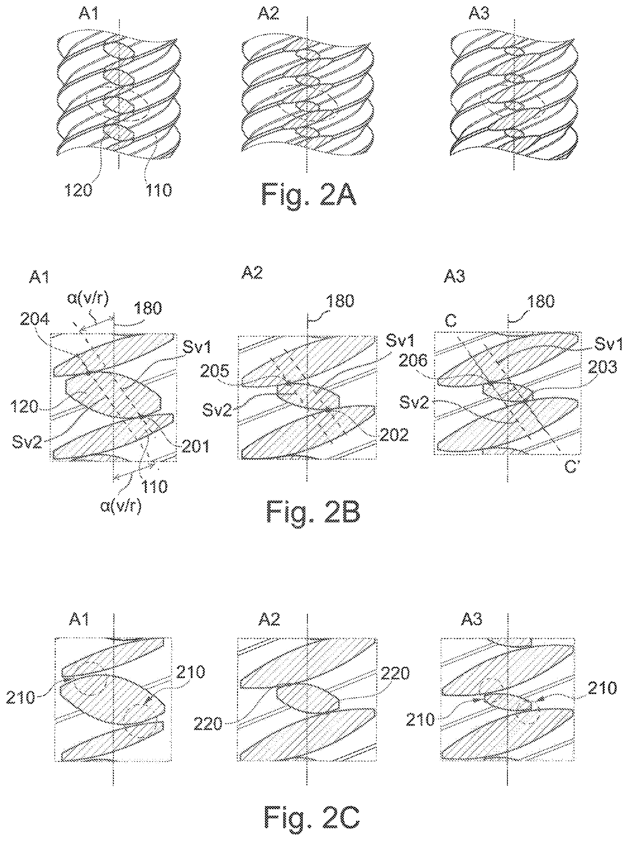
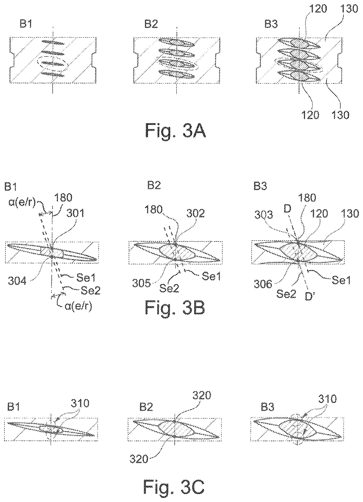
[0076]The second embodiment differs from the first embodiment in that the threads of the rollers have concave or convex flanks and come into contact with the threads of the screw and of the nut along curve segments, rather than along straight line segments.

[0077]In the situation of contact between two helical surfaces (outside surface of a screw or of a roller or inside surface of a nut) taking place along a curve segment, the contact plane is the plane containing said curve segment. In the roller screw mechanism of the invention, this contact plane is distinct from the plane that is common to the longitudinal axes of the two helical surfaces. Unlike when the contact takes place along a straight line segment, there is no tangential plane common to the two helical surfaces and also containing said curve segment.

[0078]In this embodiment, when the threads of the rollers have concave flanks, the threads of the screw and of the roller have convex flanks....


PUM


Abstract

The invention relates to a roller screw mechanism comprising a screw (110) provided with an external thread; a nut (130) coaxially surrounding the screw (130) and provided with an internal thread; and rollers (120), each of which is provided with an external thread, each roller (120) being interposed between the screw (110) and the nut (130) so that the threads of the rollers mesh with the threads of the screw and of the nut; said roller screw mechanism being characterized in that the threads of the rollers are complementary to the threads of the screw and of the nut so that, at zero load, the threads of the rollers co-operate on both of their flanks with the threads of the screw and of the nut in a contact geometry having curvilinear segments.

Description

RELATED APPLICATIONS[0001]This application is the U.S. National Stage of International Application No. PCT / FR2018 / 051447, filed Jun. 18, 2018, which designates the U.S., published in French, and claims priority under 35 U.S.C. § 119 or 365(c) to French Application No. 17 555 68, filed Jun. 19, 2017. The entire teachings of the above applications are incorporated herein by reference.TECHNICAL FIELD[0002]The invention relates to the field of roller screw mechanisms, which make it possible to transform a movement in rotation into a movement in translation, and vice versa.PRIOR ART[0003]A roller screw mechanism typically comprises a screw, a nut disposed coaxially around the screw, and a plurality of rollers interposed between the screw and the nut, and having their longitudinal axes parallel to the axis of the screw. The screw and the rollers are provided with external threads, and the nut is provided with an internal thread. The threads of the rollers are in engagement with the thread...

Claims


Application Information

Patent Timeline
Patent Type & Authority Patents(United States)
IPC IPC(8): F16H25/20F16H25/22
CPCF16H25/2252
Inventor DUBUS, JÉRÔME
Owner DUBUS JEROME
Why Eureka
Try Eureka